a b -b- 
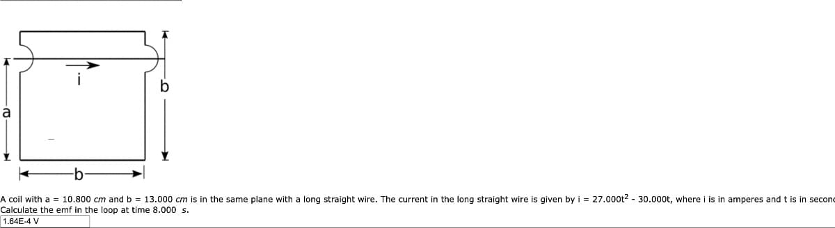
A coil with a 10.800 cm and b = 13.000 cm is in the same plane with a long straight wire. The current in the long straight wire is given by i = 27.000t² - 30.000t, where i is in amperes and t is in secon Calculate the emf in the loop at time 8.000 s. 1.64E-4 V
Q: 2. According to circuit below calculate values for RF, VOUT and VCE in case of the relay is…
A: Given parameters VBE=0.8vbeta=100Relay=12v/200ohmR1=R2=R3 =10kohm
Q: Build a ladder and wiring diagram Circuit A. One lampholder and one duplex receptacle…
A: The objective of the question is to create a ladder and wiring diagram for three different circuits.…
Q: 4s+2 G(s) = s3+4s2+5s+2 Convert the transfer function to state space in Jordan canonical
A: The transfer function of a system is given by⇒G(s)=4s+2s3+4s2+5s+2 ;We need to convert the transfer…
Q: Find I PRACTICE PROBLEM 9 14 Ω -30 822 j5Q 30/0° V www m 50 10 Ω -120
A: Given circuit: -Find: -Current =?
Q: How is hysteresis detected in instruments? illustrate the effect of hysteresis on a instrument? what…
A: 1. Hysteresis in instruments is detected by observing differences in readings when the input changes…
Q: a 6uF capacitor with an initial potential difference of 17V is discharged through a resistor when a…
A: Given that,The capacitance, ;Initial potential difference,;From given problem, draw the the circuit…
Q: Find the Norton equivalent of the following circuit with respect to the terminals a and b. a) What…
A: Norton's Theorem states that any linear electrical network with multiple voltage and current sources…
Q: 2.3
A: Fourth option is correct.Explanation:
Q: 9.6 Using D flip-flops, design a logic circuit for the finite-state machine described by the state…
A:
Q: 2. For the SSBSC modulator shown below: (A=5, B=0.2, C=0.01) a) identify the method of single…
A: Given:we need to do:a) identify the SSB-SC generation. b) Find the equation at the output of BM1,…
Q: If Vs = 8 V, R1 = 13 Q2 and R2 = 62 2, what voltage would you expect to see displayed on a voltmeter…
A: Voltage divider rule, is a fundamental principle in electrical engineering used to determine the…
Q: For the below circuit find the following: 30 Ω www 0.4 H m www 40 V 1=0✗ 50 Ω a) V(0) equals b) Alph…
A: An RLC transient circuit Find the valu of a. voltage across the capacitor.b. alpha(a)c. value of…
Q: Determine the Fourier coeficients a0, an, bn, and Dn of the following periodic funtion f(t):
A: Given:we need to determine:Fourier series coefficients.
Q: (HW) Q1: Calculate the real and reactive power absorbed by every element (including the sources) in…
A: The given circuit diagram is shown below,
Q: 1.4
A: The voltage obtained is: VL(t)=−s900mVe(−s300t) Note the final value depends upon the value of…
Q: What type of safety components would be used in a typical nursing home and how do they operate?…
A: Safety components in a nursing home are crucial for ensuring the well-being and security of…
Q: 1. Hill Given the following circuit: R1 w 3Ω V1 12 V ·ទ 5Ω R2 w R3 4Ω Determine: a. R1, R2, R3, IR4,…
A: The circuit diagram,
Q: Given that Vs = 3 V, R₁ = 12, and R₂ = 30, what is the maximum current Is for which the current…
A:
Q: 5.2. Figure below shows a R - 2R trapezoid circuit network used for DA signal transformation, try to…
A:
Q: A customer has sent in a transformer for repair, with the following information on its nameplate: Dz…
A: The "Dz 6" on the transformer's nameplate likely indicates its specifications, potentially including…
Q: Needs Complete typed solution with 100 % accuracy.
A: The objective of this question is to determine the readings on an ideal ammeter and voltmeter in a…
Q: In the given circuit, &₁ = 15 V, &2 = 5 V and 83 = 10 V. The resistance of each resistor is 102.…
A: The circuit diagram,
Q: 3. Use source transformation technique to find current io flowing through 6k2 resistor.
A: Note:- We are allowed to solve one question at a time. Therefore, providing the solution for the…
Q: Problem 7-4: Design a cascading LC low-pass filter with maximally flat magnitude response. Use a…
A: cut off frequencyDesigned the cascading LC low pass filter.
Q: double sideband supressed carrier problem.
A: Given:we need to draw the frequency spectrums at points A, B and C.
Q: 8. Consider the table below. A, B, C represent logic-variable input signals. F is an output. ABCF…
A: AnswerGiven Truth table:No A B C F0000010010201013011041000510116110071111Where A, B, and C…
Q: 6. Show the connection of two 741 op-amp stages to provide outputs that are 15 and -30 times larger…
A:
Q: 2.4
A: Detailed solution is peovided below.Explanation:
Q: Q3. (a) Determine the flux crossing a 1mm x 1mm area on the surface of a cylindrical shell in Fig.…
A: (a) -4 uC(b) Meaning of negative answer is that flux lines are radially inwards pointing towards…
Q: find the truth table for this circuit , thank you in advance
A: The given logic circuit isWe need to determine the truth table for the logic circuit.
Q: Two of the circuits will be a 3-wire, multi-wire branch circuit (Edison 3-wire). The location of…
A: The objective of the question is to understand how to design and implement three different…
Q: find skin depth of a conductor with 10 mho/m at a frequency of 10mhz.
A: We need to find out skin depth for given conductor.
Q: Example 7.28 In the RC circuit shown below, the capacitor has an initial charge qo = 2500 μC. At…
A:
Q: Find the Equilance resistance btw A & B R1 70 A o www BO ៥៩ 6Q m R3 12 Ω 122 mn
A: To calculate the equivalent resistance between A and B
Q: What are the expected readings of the following in the figure below? (R = 7.200, AV = 5.30 V) Save w…
A: Given:with we need to find:a) ammeter readingb) voltmeter readingc) we also need to find the…
Q: Half-wave 50Hz sinusoidal uncontrolled rectifier circuit with a peak voltage value of 100V and a…
A: For a half-wave rectifier circuit,
Q: Two resistive loads are connected in series. Load 1 has a resistance of 1000 ohms while load 2 has a…
A: The given data is shown below:
Q: Needs Complete typed solution with 100 % accuracy. Don't use chat gpt or ai i definitely…
A: The objective of the question is to find the inductance (L) of the LCR circuit at the resonant…
Q: This is a practice problem from my Introduction to Electronics course. Could you please walk me…
A: We have verified that given transistor is operation in Forward active region . Here we have also…
Q: Q8. Show the resultant of the two waves yi A sin [wt-k(x+Ax)] Y2A sin (wt-kx) 2Acos (kAx/2) sin…
A: To find the resultant of the two waves y1 and y2,We can add them together y = y12
Q: The specific resistance is defined as Select the correct response: Resistance of any conductor at 20…
A: The specific resistance is defined as------a. Resistance of any conductor at 20 degrees Celsius.b.…
Q: What is the thevenin voltage and resistance of the circuit below across nodes a and b? Node b is…
A: Vth=50 V, Rth=6 ohmExplanation:Step 1:Step 2:Step 3:Step 4: Thevenin Circuit:
Q: The circuit in the image given below is a differential amplifier driven by a bridge. Find Vo Given…
A: Given the circuit:Given R0=80 k.We need to find the value of .
Q: 4- [G]= 1 0 0 1 1 0 1 1 0 0 Find the following: 01001 101 10 0010011101 a- Find the [H] matrix. b-…
A: To solve this problem, we need to understand the concept of linear block codes and the Hamming…
Q: The switches shown in the diagram have been in this position for a long time prior to t = Os, use…
A: The current is IL(t)=(20+80e-500t)mA for 0<t<2 sec, IL(t)=(30-10e-250(t-2) )mA for t>2…
Q: 2.16. Use Euler's relation to with the following functions in the form x(t) = A cos (wol + ).
A: x(t)=5cos(4πt+36.86) is the form of x(t)=Acos(w0t+ϕ) for given function…
Q: Simplify the following and draw logic diagram using NOT, AND, OR Gates Y = A'B'C' + A'BC'+A'BC+AB'C
A: The given data is shown below:
Q: Simplify the circuit below to find the equivalent resistor Rab.
A: The given data is shown below:
Q: The steady-state voltage drop between the load and the sending end of the line seen in (Figure 1) is…
A: The given circuit diagram is shown below,
Q: Provide an advantage of assembling three single phase transformers into a three phase bank vs:…
A: One advantage of assembling three single-phase transformers into a three-phase bank compared to…
Trending now
This is a popular solution!
Step by step
Solved in 3 steps with 3 images
- For a motor design, you need to design a solenoid coil that produces a magnetic flux density (B) of at least 2000 gauss when a 10 mA current flows through the conductor. Due to space limitations, the coil only can be 10 turns over a 1 cm length. To obtain the needed performance, go to Table 3 and choose a core material for the coil.The figure is a cross section through three long wires with linear mass density 58.0 g/m. They each carry equal currents in the directions shown. The lower two wires are 4.0 cm apart and are attached to a table. What current I will allow the upper wire to "float" so as to form an equilateral triangle with the lower wires?I need this answer the subject is dc machine
- Q-1: Give brief answer to the following: (Answer Ten only)1) what is the potential transformer used for in power substation?2) what is process leads to lowering the number of free electrons?3) what is The Townsend’s Criterion4) why Sulphur Hexafluorid has good insulation strength?5) What is Intrinsic Breakdown6) why do bubbles lead to breakdown of liquid?7) how to decease the ripple voltage of cockroft-walton voltage multiplier circuit8) how much the maximum charging current of A Van de Graaff generator has a beltwidth 1 m, a belt speed of 4 m/s, and charge density of 10 c/m29) Why does need for Reactive Power Compensation in test transformer?10) The output voltage of series resonant circuit is given by the formula _________11) what is impulse voltage and what is its standard wave shape?12) Which advice can measure impulse voltage?The circuit shown in the given figure is a model of a solenoid, such as that used to engage the gear of a car’s starter motor to the engine’s flywheel. The solenoid is constructed by winding a wire around an iron core to make an electromagnet. The resistance R is that of the wire, and the inductance L is due to the electromagnetic effect. When the supply voltage vs is turned on, the resulting current activates the magnet, which moves the starter gear. Obtain the model of the current i given the supply voltage vs.Determine the force acting on the movable part in Figure P3.7 when the 100-turn coil carries a current of 20 A. The relative permeability of the mag- netic material is 1000.
- A rectangular loop carrying current I2 is placed parallel to an infinitely long filamentarywire carrying current I1 as shown in figure. Show that the force experienced by the loopis given byAn electric toothbrush has a base designed to hold the toothbrush handle when not in use. As shown, the handle has a cylindrical hole that fits loosely over a matching cylinder on the base. When the handle is placed on the base, a changing current in a solenoid inside the base cylinder induces a current in a coil inside the handle. This induced current charges the battery in the handle. We can model the base as a solenoid of length ℓ with NB turns (as shown), carrying a current i, and having a cross-sectional area A. The handle coil contains NH turns and completely surrounds the base coil. Find the mutual inductance of the system.An ideal core (assume relative permability is infinity) with a crossectional area of 12 cm2is excited via10A current flowing through coil with 200 turns. On the one side of the coil, a 1 cm long paramagneticmaterial (µr=1) is placed. Calculate the magnetic field on paramagnetic material
- Please answer this NEATLY, COMPLETELY, and CORRECTLY for an UPVOTE. Jusr answer letters d, e, f. A cable hangs between two poles that are 80-ft apart. The two poles are both 40 foot high. Sag is observed in the middle of the cable 5 ft from the ground. Find the length of the cable. d. What is the general equation for length of the cable S?e. What are the boundary conditions for finding the total length of the cable S?f. What is the length of the cable S?***Note!For your basis, here are the questions for letters a-c which have already been answered in this link (https://www.bartleby.com/questions-and-answers/cable-hangs-between-two-poles-that-are-80-ft-apart.-the-two-poles-are-both-40-foot-high.-sag-is-obse/552ca7ad-6b18-4584-bd7a-02bbebcb1f20):a. What is the working equation for a catenary forming cable?b. What is the computed constant a up to 4 decimal places?c. What is the catenary equation for the given problem?5. Suppose we go around the loop counterclockwise, starting from point a and return to the starting point, what happens to the total electric potential? 6. As we go around the loop counterclockwise measuring potential differences across the circuit elements as we go. Use (+) sign for a potential increase and (-) for a potential drop. Write am equation for the travel we traced.Consider the circuit shown in Figure P14.36. The two coils have L1=0.1 H, L2=10 H, and M=0.5 H. Prior to t=0, the currents in the coils are zero. At t=0, the switch closes. Determine and sketch i1(t) and i2(t) to scale versus time.