A single-bay frame of the type illustrated in Figure 9.5 carries a horizontal load of 5000 lb acting at the upper-left joint. Assume that h = 15 ft and L = 25 ft. Draw shear and moment diagrams. Indicate numerical values. Use an approximate method of analysis
A single-bay frame of the type illustrated in Figure 9.5 carries a horizontal load of 5000 lb acting at the upper-left joint. Assume that h = 15 ft and L = 25 ft. Draw shear and moment diagrams. Indicate numerical values. Use an approximate method of analysis

Chapter2: Loads On Structures
Section: Chapter Questions
Problem 1P

Related questions
Question
100%
A single-bay frame of the type illustrated in Figure 9.5 carries a horizontal load of 5000 lb
acting at the upper-left joint. Assume that h = 15 ft and L = 25 ft. Draw shear and
moment diagrams. Indicate numerical values. Use an approximate method of analysis.
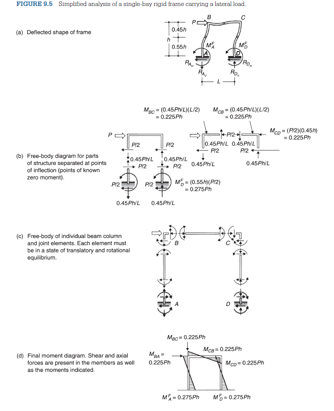
Transcribed Image Text:FIGURE 9.5 Simplified analysis of a single-bay rigid frame carrying a lateral load.
(a) Deflected shape of frame
B
0.45h
MA
M
0.55h
RA
IRON
=
MCD (P/2)(0.45h)
(b) Free-body diagram for parts
of structure separated at points
of inflection (points of known
zero moment).
робра
RAV
Mac (0.45Ph/L)(L/2)
= 0.225Ph
P/2
P/2
0.45Ph/L 0.45Ph/L
Rov
MCB (0.45Ph/L)(L/2)
= 0.225Ph
0.45Ph/L 0.45Ph/L
P/2
P/2
0.45Ph/L
0.45Ph/L
P/2
P/2
P/2
P/2
M = (0.55h)(P/2)
= 0.275Ph
0.45Ph/L 0.45Ph/L
(c) Free-body of individual beam column
and joint elements. Each element must
be in a state of translatory and rotational
equilibrium.
(d) Final moment diagram. Shear and axial
forces are present in the members as well
as the moments indicated.
MBC= 0.225Ph
MCB=0.225Ph
MBA
0.225Ph
MCD = 0.225Ph
MA=0.275Ph
M=0.275Ph
= 0.225Ph
Expert Solution
This question has been solved!
Explore an expertly crafted, step-by-step solution for a thorough understanding of key concepts.

This is a popular solution!
Step 1: Introduce the problem statement
VIEWStep 2: Determine axial force in columns
VIEWStep 3: Determine shear force in columns
VIEWStep 4: Compute beam shear force
VIEWStep 5: Compute beam and column moments
VIEWStep 6: Plot free body diagram
VIEWStep 7: Plot shear force diagram
VIEWStep 8: Plot bending moment diagram
VIEWSolution
VIEW
Trending now
This is a popular solution!

Step by step
Solved in 9 steps with 19 images

Knowledge Booster


Learn more about
Need a deep-dive on the concept behind this application? Look no further. Learn more about this topic, civil-engineering and related others by exploring similar questions and additional content below.Recommended textbooks for you

Structural Analysis (10th Edition)
Civil Engineering
ISBN:
9780134610672
Author:
Russell C. Hibbeler
Publisher:
PEARSON

Principles of Foundation Engineering (MindTap Cou…
Civil Engineering
ISBN:
9781337705028
Author:
Braja M. Das, Nagaratnam Sivakugan
Publisher:
Cengage Learning
Structural Analysis (10th Edition)
Civil Engineering
ISBN:
9780134610672
Author:
Russell C. Hibbeler
Publisher:
PEARSON
Principles of Foundation Engineering (MindTap Cou…
Civil Engineering
ISBN:
9781337705028
Author:
Braja M. Das, Nagaratnam Sivakugan
Publisher:
Cengage Learning

Fundamentals of Structural Analysis
Civil Engineering
ISBN:
9780073398006
Author:
Kenneth M. Leet Emeritus, Chia-Ming Uang, Joel Lanning
Publisher:
McGraw-Hill Education


Traffic and Highway Engineering
Civil Engineering
ISBN:
9781305156241
Author:
Garber, Nicholas J.
Publisher:
Cengage Learning