

Q: 210 x(n) 4 d 5 + In 2 9 10
A: Given the discrete time signal.
Q: PROBLEM NO. 2 A Three-Phase Transmission Line has three conductors spaced equally at 2 meters apart.…
A: The configuration shown in the question is of equilateral spacing of conductors in which the…
Q: Problem 3. Find the transfer function, V₁(s)/V(s), for the electrical network shown in Figure 3,…
A:
Q: 4. Using a Karnaugh map, simplify the function F (A, B, C, D) = Σ (0, 2, 3, 6, 7, 8, 10, 11, 12,…
A:
Q: Given that V₁ = -15V and V₂ = 26V, what is V3? + V3 w V₁ V₂
A: Given data, V1=-15 V, V2=26 V. Circuit diagram is given as,
Q: Q. 1 ) (n+12) power 2 perform the indicate operation
A: Basic operation:
Q: Two coupled coils have self-inductances of 500 mH and 750 mH, respectively. If the coefficient of…
A:
Q: 5 10 3k ZZK ik find the thevenin equivalent circuit isolating the diode ☆
A: The equivalent circuit can be solved as following.
Q: 2.9 Which of the circuits in Fig. 2.66 will give you Vab = 7 V? 3 V 3 V +1 SV 1 V (a) 5 V ob Joa 1 V…
A:
Q: Assuming Vtp=-1V. Vx and Vy=5V at time 0, and the capacitor is initially charged to 5V. ignoring the…
A: This question deals with p-channel MOSFET which conducts like a switch iff |Vsg|>|Vtp|…
Q: Find the current that passes through the 19 resistor. A 46 6V @ D 352 www E Iz I₂ F 19 www 222 •…
A: We will apply kirchoffs rule here 1- current rule - at any junction or node incoming current must…
Q: Required information Problem 06.033 Section Break Consider the circuit given below. Ven +5 V Problem…
A: In this question We need to determine the value of collector current in mA. We know VBE ON = 0.7V…
Q: i = I sin(Ⓡt + ; ) $; V = V sin(ot+) Z
A: Given data, Voltage V=3458.8∠31.70 V. Current I=208.3∠540 A.
Q: Problem 2. Derive an expression for Vo as a function of V₁₁ and V₁2. 50 ΚΩ Μ ότι ο Μ 20 ΚΩ UROM 40…
A:
Q: Caleulate the de output voltage in Fig
A: These given circuits are voltage multiplier circuits as shown their output. We can find dc output…
Q: Is there a way to determine whether a component of the system should be considered a source or a…
A: We need to determine whether a component of the system should be considered a source or a sink.
Q: How can regulate rotational speed of an AC motor?
A: We need to tell about regulate rotational speed of an AC motor.
Q: In a series L-C circuit, the inductance and capacitance are 5 H and 2 μF respectively. of the…
A: Given data, Inductance L = 5 H. Capacitance C=2 μF.
Q: ellee D₁ Vost D₂ Figure 4-2. Full wave (center-tapped) rectifier circuit.
A: 1(a).given that center-tapped full wave rectifier circuit To draw schematic foe the given condition…
Q: RB www IB B IB +VCC=20V IC VBE 1 kohm C E VCE
A:
Q: x(t) = ³300nt Find the average signal power of x(t). The average signal power of x(t) is
A: In this question We need to determine the power of the given signal. We know power of the signal…
Q: A factory is supplied by a single-phase network of 220 V - 50 Hz. It contains in parallel: - 2…
A: As per the guidelines given to us, we can only provide the solution to the first three subparts of…
Q: b) If a 5V voltage source is connected at port 1 and a 500 resistor is connected at port 2. Find the…
A:
Q: Problem 1 ; (t) = 5 sin (40€ +15°) v (t) = 50 cos (yot) i) Find load Impedance ii) Find the complex…
A: (1). given that circuit has voltage source v(t ) =50cos(40t) = Vmcos(ωt) current…
Q: A typical ceiling fan on medium speed rotates at a frequency of 150 rpm (revolutions per minute).…
A: The given value of speed of a typical ceiling fan at a frequency is Nr=150 rpm. We need to determine…
Q: 3. Use Venn diagrams to prove whether or not x(y + 2) = xy + xyz.
A: The venn diagram is solved below.
Q: Determine internal bias voltage vont V-=-15 V+=15
A: Op-amp is multistage amplifier. The ideal op-amp have infinite input resistance and infinite gain.…
Q: Derive the expressions for the ripple voltage and DC voltage of capacitor filter half-wave rectifier…
A: Given data A Half wave rectifier and full-wave rectifier with a capacitor filter are given in the…
Q: Q2. The switch has been closed for a long time. At t = 0, the switch is opened. What is the voltage…
A:
Q: (4 6 2K 3k 4k =7 5 k 59 find the power burned in the 3k resistor
A:
Q: The current through a 20-mH inductor is shown in Fig. 9. Sketch the voltage across the inductor.…
A:
Q: The step response of a time LTI system continuous is given by (1-e-t )u(t). For some unknown input…
A: In this question We need to determine the input if output is given. We are solving this problem…
Q: Which matrix equation correctly represents the network?
A: Given a network of the one-way street. The variables through x1 to x5 represent the number of cars…
Q: Is there a list of potential problems that might occur with various forms of electronic…
A: Electronic communication: Electronic communication refers to any type of communication that is…
Q: Q6/ Determine the values of the capacitance, C1, and of the resistances, R1 and R2 for the circuit…
A:
Q: Q3/ a) Find the admittance Y parameters for the network shown below 125 02 V₁ 500 750 V/₂
A:
Q: Q3: for Figure 3.96, find voltage vo, using: a) Nodal analysis b) Mesh analysis
A: The node and mesh equation can be obtained by applying kirchhoff's current and voltage law to the…
Q: 5. The op amp in the adder-subtractor circuit is ideal. Find the output voltage v, if va = 2V, vb =…
A:
Q: Two 60Hz alternators are driven by shunt motors. The shunt motors have speed-load droop…
A: Please refer the attached images for the complete answer
Q: (3) Det. VBB to ensure that transistor is saturated. Let Re-100k2, Re-3k2, Vcc=+10V, B=100 and…
A:
Q: Write an essay about which types of problems can be solved by using finite state machines.
A: Algorithmic test pattern generating testing for the circuit under test uses finite state machines.…
Q: A three phase half-wave-controlled rectifier has voltage source equal to 230V supplies a load of 5kW…
A: Given: In this question, the given details are, A three phase half-wave-controlled rectifier has…
Q: 6 A TISIM V₁40 0 11 Use the node-voltage method to find v₁ and v2 the circuit in Fig. P4.11. Figure…
A:
Q: . The following f(x) in a Fourier series of period 4. f-1, 0<x<2 1 2<x<4 »={;"
A: In this question We need to determine the Fourier series of the given signal. We know wo = 2π/T
Q: A resonant circuit has a BW of 363 rad/s and a quality factor of 39. What is the resonant frequency…
A: Given data Band width B.W=363 rad/sec Quality factor Q= 39 Resonant frequency fr = ?
Q: In the RL circuit shown below the total series impedance is known to be R =0.8 22 and L = 21.22 mH.…
A: Given parameters R = 0.8 ohm L =21.22 mH V(t) =20000 sin 377t+α here , ω =377 rad/sec Vm =20000
Q: (b) A single-phase transformer is rated at 200V/1000V. The secondary voltage of the transformer is…
A: Since you have asked multiple questions in a single request, we will be answering only the first…
Q: Using the Laplace transform, calculate the convolution y(t) = x(t)∗h(t) of the pair of signals.
A: In this question We need to determine the output of the given signal. We are solving this problem…
Q: 3.59 Consider the following vector fields: A = xa+ya, + za₂ B = 2p cos pa, - 4p sin da, + 3a₂ C =…
A: Given 3 vector fields A, B and C To find if they are solenoidal and rotational.
Q: You determine the slope of the F vs. V2 graph to be 0.00000000238 C2/Nm2. The length and width of…
A: Given data: The slope of the F vs V2 graph isFV2=0.00000000238 C2Nm2=2.38×10⁻⁹ C2Nm2. The length of…

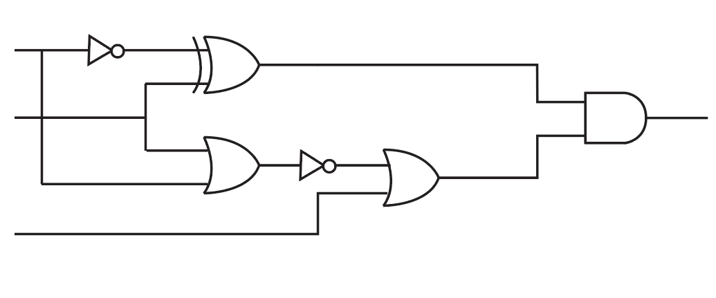
consider the following image provided of a logic circuit. Labell all inputs so the output of the circuit is a'c.

The given logic circuit is shown below,

Step by step
Solved in 2 steps with 2 images


- From the BCD code whose block diagram is given in the figure below, you can find the 7-segment LED display (with common anode) code. Solving combinational logic circuit will be designed. This type of commercially produced decoder is integrated State the features you consider important by researching the circuits. BCD input at the output of the decoder For the 0-9 values of the information information, the following display figures will be seen and the values other than these it will be considered arbitrary. Since the 7-segment LED display has a common anode, Logic "0" will be applied in response to the burned parts. The accuracy of the logic circuit you will design Create the table and find the output expressions by shrinking the table with the Karnaugh diagram method.From the BCD code whose block diagram is given in the figure below, you can find the 7-segment LED display (with common anode) code. Solving combinational logic circuit will be designed. This type of commercially produced decoder is integrated State the features you consider important by researching the circuits. BCD input at the output of the decoder For the 0-9 values of the information information, the following indicator figures will be seen and the values other than these it will be considered arbitrary. Since the 7-segment LED display has a common anode, The logic "0" will be applied to the burned parts. Draw this circuit.Write a VHDL program to implement the combinational logic circuit in the following figure. HA A>B A>E B The circuit contains three input signals r, q and s, and one output sigal z. All signals are 1 bit only. In the circuit, there are two 2-to-1 multiplexers and two 2-input comparators. The two comparators should be implemented using component.
- From the BCD code whose block diagram is given in the figure below, you can find the 7-segment LED display (with common anode) code. Solving combinational logic circuit will be designed. This type of commercially produced decoder is integrated State the features you consider important by researching the circuits. BCD input at the output of the decoder For the 0-9 values of the information information, the following indicator figures will be seen and the values other than these it will be considered arbitrary. Since the 7-segment LED display has a common anode, Logic "0" will be applied to the burned parts. The accuracy of the logic circuit you will design Create the table and find the output expressions by shrinking the table with the Karnaugh diagram method.4. For the logic circuit shown in Figure below write the required input condition (A,B,C) to make the output X =1. A BDesign the following combinational logic circuit with a four-bit input and a three-bit output. The input represents two unsigned 2-bit numbers: A1 A0 and B1 B0. The output C2 C1.C0 is the result of the integer binary division A1 A0/B1 B0 rounded down to three bits. The 3-bit output has a 2-bit unsigned whole part C2 C1 and a fraction part CO. The weight of the fraction bit CO is 21. Note the quotient should be rounded down, i.e. the division 01/11 should give the outputs 00.0 (1/3 rounded down to 0) not 00.1 (1/3 rounded up to 0.5). A result of infinity should be represented as 11.1. A minimal logic implementation is not required. (Hint: start by producing a truth table of your design).
- Simplify the following function and draw a logic circuit using,DO NOT COPY ANSERWS IT'S INCORRECT A very detailed solution and if you can use a program to design after the work please do.Problem : Design a circuit that takes a 3-bit number and increments it by two using a minimum number of 4x1 Mux's and a minimum number of logic gates the output is 4 bits. Show your work and label all inputs/outputs appropriately.Consider the circuit below. The switches are controlled by logic variables such that, if A is high, switch A is closed, and if A is low, switch A is open. Conversely, if B is high, the switch labeled is open, and if B is low, the switch labeled is closed. The output variable is high if the output voltage is 5V, and the output variable is low if the output voltage is zero. a. Write a logic expression for the output variable. b. Construct the truth table for the circuit. A Logic 1 5V(+ B C Logic 0 R
- Design a logic diagram to display a digit 5 using 7-segment displayquestion from DIGITAL LOGIC DESIGN book Sequential Logic :2. Perform Analysis Procedure on the following Circuit. Finally, do not forget to comment on the behaviorof the circuit. Perform all necessary analysis steps.and aslo perform each step.Write a VHDL code for the following simple logic circuit. D- X1 X2 f X3