Consider the 1-flip-flop circuit with external input L, M described below. Inputs L M 0 1 0 1 0 0 1 1 next output Q* Q Q' 0 1 no change toggle reset set (a) Determine the characteristic equation of the above circuits. (b) Draw a state diagram for the circuit. Use transition expressions in your state diagram; that is label the arrows in the state diagram with Boolean expressions that must evaluate to 1 if the arrow is to be followed. (c) Write two Verilog code for the circuit. One of the codes must be based on the characteristic equation, and the other must be based on the given charateristic table.
Consider the 1-flip-flop circuit with external input L, M described below. Inputs L M 0 1 0 1 0 0 1 1 next output Q* Q Q' 0 1 no change toggle reset set (a) Determine the characteristic equation of the above circuits. (b) Draw a state diagram for the circuit. Use transition expressions in your state diagram; that is label the arrows in the state diagram with Boolean expressions that must evaluate to 1 if the arrow is to be followed. (c) Write two Verilog code for the circuit. One of the codes must be based on the characteristic equation, and the other must be based on the given charateristic table.

Chapter22: Sequence Control
Section: Chapter Questions
Problem 6SQ: Draw a symbol for a solid-state logic element AND.

Related questions
Question
100%
please answer all parts, part 3 corresponds with the answer from part 1

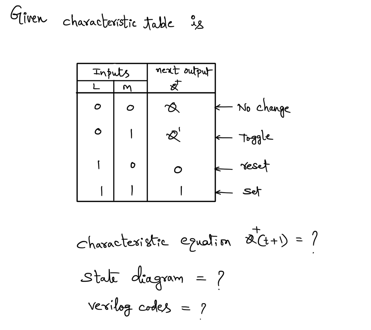
Transcribed Image Text:Consider the 1-flip-flop circuit with external input L, M described below.
Inputs
L M
0
1
0
1
0
0
1
1
next output
Q*
Q
Q'
0
1
no change
toggle
reset
set
(a) Determine the characteristic equation of the above circuits.
(b) Draw a state diagram for the circuit. Use transition expressions in your state
diagram; that is label the arrows in the state diagram with Boolean expressions
that must evaluate to 1 if the arrow is to be followed.
(c) Write two Verilog code for the circuit. One of the codes must be based on the
characteristic equation, and the other must be based on the given charateristic
table.
Expert Solution
Step 1

Trending now
This is a popular solution!

Step by step
Solved in 4 steps with 4 images

Knowledge Booster


Learn more about
Need a deep-dive on the concept behind this application? Look no further. Learn more about this topic, electrical-engineering and related others by exploring similar questions and additional content below.Recommended textbooks for you