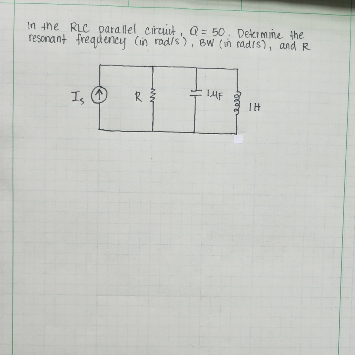
In the RLC parallel circuit, Q = 50. Determine the resonant frequency (in rad/s), BW (in rad/s), and R Is R 3 IMF eelb HI


Q: 2. Consider the RLC circuit in Homework 1, Question 3. The values of R, L, and C are given as: R =…
A: However, based on the information you provided about the circuit, I can help you analyze it and…
Q: Calculate the magnetic flux created by the field lines uniform magnetic force of 27 passing through…
A: Thank You !
Q: Example:find an expression for Vc,ic, Vr for the circuit ? 40V 1=0 SKA 4BF
A: Thank you
Q: Please answer in typing format for
A: Step 1: Step 2: Step 3: Step 4:
Q: 어떻게 문제에 접근해야할지 모르겠어요 접근 방법과 풀이과정을 자세하게 알려주세요
A: Step 1:Step 2:Step 3:
Q: Determiner and sketch the output y (t) of a LTI system with input signal x (t) and the impulse…
A: References; Duhamel, P. E. (2017). Low-Mass and Low-Power Optical Flow Sensing and Control for…
Q: Why was the smoothing capacitor C1/47 not placed directly after the unit bridge? It was placed in…
A: here's a possible explanation for why the smoothing capacitor C1/47 was not placed directly after…
Q: Find v0 if it is 20 V using source transformations.
A: Step 1: Step 2: Step 3: Step 4:
Q: Can you check if the answser that I did in each question is correct? (a) Determine τ τ = 66.67ms (b)…
A:
Q: 2 ли 2 VSA 2 3 ли 0.25m F 2 ли 2 1m H V52 VS₁ = 12 cos 10³t 3 Vs₂ = 6 sin 10³t i (t) = ?
A: KIRCHHOFFS CURRENT LAW: It states that the algebraic sum of currents entering into the node is…
Q: Calculate the convolution for the following tow functions f(t) & x(t)? x(t) (a) 2 1 2 2
A: First i write the function of f(t) and x(t) f(t)={2−t0for 0≤t≤2otherwise x(t)={10for…
Q: Please show the full steps. Thanks.
A: Step 1:
Q: show all the work
A: Step 1:Step 2:
Q: A six-pole, lap-wound, 220 V, shunt-excited d.c. machine takes an armature current of 2.5 A when…
A: Step 1:Step 2:Step 3:Step 4:
Q: 5 The electric motor shown in Figure 7.37 has field 106 Hsin 26 a, A/m P Calculate the flux per pole…
A:
Q: quetion 5
A: Step 1:Step 2:Step 3:Step 4:
Q: (a) Assuming that the network below is in steady state prior to t = 0, find i(t) for t > 0. = 0 i(t)…
A: Step 1: Step 2: Step 3: Step 4:
Q: Please answer in typing format
A: In-Depth Analysis of the Hand-Drawn RC Circuit with InductorBased on the description you provided,…
Q: Please show all work and steps like eq1 and 2, etc. Thank you
A:
Q: each, 30 pts) 3- For the Boolean function F = wx'y + wy'z + wyz' + w'y'z + xy (a) Obtain the truth…
A: a) To obtain the truth table of the Boolean function F = wx'y + wy'z + wyz' + w'y'z + xy and…
Q: Find V0 please answer in typing format
A: Step 1: Step 2: Step 3: Step 4: Step 6
Q: Question 5 [home exercise]: Complete the following diagrams showing which switches are closed and…
A:
Q: 4. Consider the following periodic waveform (t). It is desired to find its Fourier series…
A: Step 1:Step 2:Step 3: Step 4:
Q: In this problem, we are interested in designing an FIR filter with input-outputrelationshipy[n] =…
A: a) To design the FIR filter with the given specifications, we can start by writing the filter's…
Q: Please answer in typing format
A: Step 1: Step 2: Step 3:
Q: A balanced three-phase load consists of three coils, each of resistance 4 Ω and inductance 0.02 H.…
A:
Q: (1) The magnetic vector potential of a current distribution in free space is given by, find: A = 15…
A: Step 1:
Q: Please answer in typing format for
A: To determine the Q point (quiescent point) of the given circuit, we need to find the operating point…
Q: 3. Consider the circuit in the figure below. The circuit includes two batteries and three currents…
A: Step 1: Step 2: Step 3: Step 4:
Q: List five (5) rules that should be adhered to in order to ensure an effective tracking and…
A: 1. Establish Clear Objectives: Clearly outline the project's goals and identify the key performance…
Q: Provide complete solution of the given problem in the image.
A: Step 1:
Q: 8.46 The switch in the circuit shown in Fig. P8.46 has PSPICE been in position a for a long time. At…
A: Step 1: Given current source in parallel with resistor. Voltage supplied by current source=…
Q: Help me Solve this plz
A: Sure, I can help you with the Laplace transform problem in the image.Applying Laplace Transform to…
Q: Consider a communication system that adopts the Automatic Repeat reQuest (ARQ) protocol. That is,…
A: a) To calculate the probability α of unsuccessful packet transmission, we need to consider the cases…
Q: Plants Draw the single line and full schematic of the Vavien (multiway switch) installation
A: In a Vavien switch (also known as a multiway switch) installation, there are multiple switches that…
Q: Q5 Consider a four-input CMOS NAND logic gate. Draw the circuit, then: Q6 a) Determine the W/L…
A: Certainly, I can help you design a circuit for the four-input CMOS NAND logic gate shown in the…
Q: show all the workk asap
A: Step 1:Step 2:
Q: For the Fig. below what is the gain margin assume k=1. R(s) 1 Y(s) Σ K (s+1)(s+2)(5+3)
A: Step 1:Step 2:
Q: Please answer in typing format
A: ANSWER:To calculate the resistor value for a given timing requirement using an RC…
Q: 7.10 A 10-kVA, 380-V, 60-Hz, 2-pole, three-phase, Y-connected, synchronousgenerator delivers the…
A:
Q: 4) 10% Derive and plot the amplitude spectrum of f (t) = sin 10t. Assume the fundamental frequency…
A: Step 1:
Q: Please help with this parctice problem so I may study
A: based on your description of the circuit being a voltage regulator with a Zener diode and a BJT,…
Q: + Phase voltage Line and phase voltage measurements Phase voltage V1N, potential difference of line…
A: Based on the image you sent, we can analyze the circuit using mesh analysis to solve for the unknown…
Q: (a) Find an expression for vo (t) fort > 0 in the circuit shown in Fig. 4 (a). 20 6 Ո 10 www www www…
A: Step 1: Step 2: Step 3: Step 4:
Q: You have been given two single-phase transformers to determine their characteristics. Using the…
A: Suggestions for Applications (limited based on available information):Transformer 1: Based on the…
Q: 2.3 Vectors p=2i+ 3j+5k and q = 3i+6k are given. Find a vector r that is perpendicular to both. 2.4…
A: Sure, Two vectors are said to be perpendicular if their dot product is zero. Therefore, to find a…
Q: 2- If the following voltage signals applied to the corresponding elements, find the currents passing…
A:
Q: 9. Suppose we design an inverting amplifier using 5% tolerance resistors and an ideal op-amp. The…
A: To calculate the minimum and maximum possible gains and the percent tolerance of the gain for an…
Q: The total capacitance that I got was: CT = 4.36uF Can you check if the answer that I got is correct
A:
Q: (a) Determine the steady-state voltage Voss (t) in the network below for t₺ > 0 if the initial…
A: Step 1:


Trending now
This is a popular solution!

Step by step
Solved in 2 steps with 1 images

- You are an electrician working in a plant. A series resonant circuit is to be used to produce a high voltage at a frequency of 400 Hz. The inductor has an inductance of 15 mH and a wire resistance of 2 . How much capacitance should be connected in series with the inductor to produce a resonant circuit? The voltage supplied to the circuit is 240 V at 400 Hz. What is the minimum voltage rating of the capacitor?For each of the driven RLC circuits specified below, do the following:i. Determine resonance properties ω0 , ωL, ωH, B, and Q (ωL and ωH are the low and high half-power frequencies).ii. Determine element values.iii. Produce a frequency responseplot for the impedance magnitudeThe inductance coil in a series resonant circuit is 0.2 H and the resistance coil is 50 Q. What is the capacitance value in the circuit that causes resonance at a frequency of 150 KHz? The source produces an emf of 100 V r.m.s.
- A series RLC circuit has 30 volt input. Resonance of circuit occurs at 333(Hz) and 3 dB bandwidth is 33(Hz). What is the magnitude value of voltage across inductor at resonance.A series RLC circuit consists of a 10Ω resistor in series with L = 10µH and C = 100µF. Determine a new value of L for which the resonant frequency is one-half the original value.A tank circuit contains a capacitor and an inductor that produce 30 Ω of reactance at the resonant frequency. The inductor has a Q of 15. The voltage of 277 V is connected to the circuit. What is the total circuit current at the resonant frequency?
- Question 02: A) How do you use Kirchhoff's law? What are the limitations of Kirchhoff's law? B) What is resonance in RLC circuit? Define the Q-factor in RLC series circuit.A parallel R-L-C circuit is fed by a constant current source of variable frequency. The circuit resonates at 100 kHz and the Q-factor measured at this frequency is 5. Find the frequencies at which the amplitude of the voltage across the circuit falls to (a) 70.7% (b) 50% of the resonant frequency amplitude.Series and parallel circuits are made from the same components as follows. A coil of resistance 300 ohm and inductance 100mH and a 4000pF capacitor are connected (i) in series and (ii) in parallel. (A) Find for each connection: (i) the resonant frequency, (ii) the Q-factor (iii) the impedance at resonance and (iv) draw the respective circuits and response curves.
- A series RLC circuit contains a resistor with a true power of 18 watts, an inductor with a reactive power of 24 VARS, and a capacitor with a reac- tive power of 34 VARS. What is the circuit power factor?What is the input impedance for this series RLC circuit? What is the reflection coefficient of the resonant circuit?In a series RLC circuit, an inductor of inductance 5 mH and a capacitor of capacitance 4 mF is present. What will be the series resonant frequency?