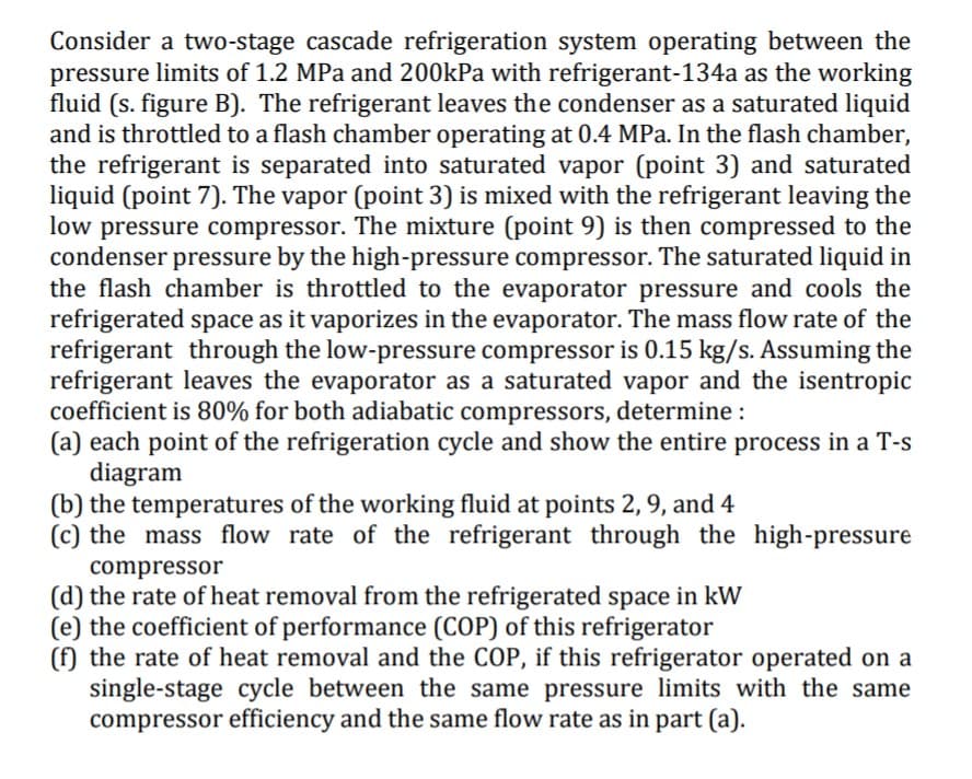
Consider a two-stage cascade refrigeration system operating between the pressure limits of 1.2 MPa and 200kPa with refrigerant-134a as the working fluid (s. figure B). The refrigerant leaves the condenser as a saturated liquid and is throttled to a flash chamber operating at 0.4 MPa. In the flash chamber, the refrigerant is separated into saturated vapor (point 3) and saturated liquid (point 7). The vapor (point 3) is mixed with the refrigerant leaving the low pressure compressor. The mixture (point 9) is then compressed to the condenser pressure by the high-pressure compressor. The saturated liquid in the flash chamber is throttled to the evaporator pressure and cools the refrigerated space as it vaporizes in the evaporator. The mass flow rate of the refrigerant through the low-pressure compressor is 0.15 kg/s. Assuming the refrigerant leaves the evaporator as a saturated vapor and the isentropic coefficient is 80% for both adiabatic compressors, determine: (a) each point of the refrigeration cycle and show the entire process in a T-s diagram (b) the temperatures of the working fluid at points 2, 9, and 4 (c) the mass flow rate of the refrigerant through the high-pressure compressor (d) the rate of heat removal from the refrigerated space in kW (e) the coefficient of performance (COP) of this refrigerator (f) the rate of heat removal and the COP, if this refrigerator operated on a single-stage cycle between the same pressure limits with the same compressor efficiency and the same flow rate as in part (a).
Consider a two-stage cascade refrigeration system operating between the pressure limits of 1.2 MPa and 200kPa with refrigerant-134a as the working fluid (s. figure B). The refrigerant leaves the condenser as a saturated liquid and is throttled to a flash chamber operating at 0.4 MPa. In the flash chamber, the refrigerant is separated into saturated vapor (point 3) and saturated liquid (point 7). The vapor (point 3) is mixed with the refrigerant leaving the low pressure compressor. The mixture (point 9) is then compressed to the condenser pressure by the high-pressure compressor. The saturated liquid in the flash chamber is throttled to the evaporator pressure and cools the refrigerated space as it vaporizes in the evaporator. The mass flow rate of the refrigerant through the low-pressure compressor is 0.15 kg/s. Assuming the refrigerant leaves the evaporator as a saturated vapor and the isentropic coefficient is 80% for both adiabatic compressors, determine: (a) each point of the refrigeration cycle and show the entire process in a T-s diagram (b) the temperatures of the working fluid at points 2, 9, and 4 (c) the mass flow rate of the refrigerant through the high-pressure compressor (d) the rate of heat removal from the refrigerated space in kW (e) the coefficient of performance (COP) of this refrigerator (f) the rate of heat removal and the COP, if this refrigerator operated on a single-stage cycle between the same pressure limits with the same compressor efficiency and the same flow rate as in part (a).

Introduction to Chemical Engineering Thermodynamics
8th Edition
ISBN:9781259696527
Author:J.M. Smith Termodinamica en ingenieria quimica, Hendrick C Van Ness, Michael Abbott, Mark Swihart
Publisher:J.M. Smith Termodinamica en ingenieria quimica, Hendrick C Van Ness, Michael Abbott, Mark Swihart
Chapter1: Introduction
Section: Chapter Questions
Problem 1.1P

Related questions
Question
please solve EF
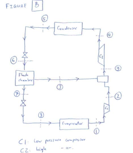
Transcribed Image Text:FIGURE
(5
Coudeuser
Flesh
chamber
(3
(8)
Evapovator
CI: Low pressare Compressor
C2: high
Transcribed Image Text:Consider a two-stage cascade refrigeration system operating between the
pressure limits of 1.2 MPa and 200kPa with refrigerant-134a as the working
fluid (s. figure B). The refrigerant leaves the condenser as a saturated liquid
and is throttled to a flash chamber operating at 0.4 MPa. In the flash chamber,
the refrigerant is separated into saturated vapor (point 3) and saturated
liquid (point 7). The vapor (point 3) is mixed with the refrigerant leaving the
low pressure compressor. The mixture (point 9) is then compressed to the
condenser pressure by the high-pressure compressor. The saturated liquid in
the flash chamber is throttled to the evaporator pressure and cools the
refrigerated space as it vaporizes in the evaporator. The mass flow rate of the
refrigerant through the low-pressure compressor is 0.15 kg/s. Assuming the
refrigerant leaves the evaporator as a saturated vapor and the isentropic
coefficient is 80% for both adiabatic compressors, determine :
(a) each point of the refrigeration cycle and show the entire process in a T-s
diagram
(b) the temperatures of the working fluid at points 2, 9, and 4
(c) the mass flow rate of the refrigerant through the high-pressure
compressor
(d) the rate of heat removal from the refrigerated space in kW
(e) the coefficient of performance (COP) of this refrigerator
(f) the rate of heat removal and the COP, if this refrigerator operated on a
single-stage cycle between the same pressure limits with the same
compressor efficiency and the same flow rate as in part (a).
Expert Solution
This question has been solved!
Explore an expertly crafted, step-by-step solution for a thorough understanding of key concepts.

Step by step
Solved in 3 steps with 36 images

Recommended textbooks for you
Introduction to Chemical Engineering Thermodynami…
Chemical Engineering
ISBN:
9781259696527
Author:
J.M. Smith Termodinamica en ingenieria quimica, Hendrick C Van Ness, Michael Abbott, Mark Swihart
Publisher:
McGraw-Hill Education

Elementary Principles of Chemical Processes, Bind…
Chemical Engineering
ISBN:
9781118431221
Author:
Richard M. Felder, Ronald W. Rousseau, Lisa G. Bullard
Publisher:
WILEY

Elements of Chemical Reaction Engineering (5th Ed…
Chemical Engineering
ISBN:
9780133887518
Author:
H. Scott Fogler
Publisher:
Prentice Hall
Introduction to Chemical Engineering Thermodynami…
Chemical Engineering
ISBN:
9781259696527
Author:
J.M. Smith Termodinamica en ingenieria quimica, Hendrick C Van Ness, Michael Abbott, Mark Swihart
Publisher:
McGraw-Hill Education
Elementary Principles of Chemical Processes, Bind…
Chemical Engineering
ISBN:
9781118431221
Author:
Richard M. Felder, Ronald W. Rousseau, Lisa G. Bullard
Publisher:
WILEY
Elements of Chemical Reaction Engineering (5th Ed…
Chemical Engineering
ISBN:
9780133887518
Author:
H. Scott Fogler
Publisher:
Prentice Hall


Industrial Plastics: Theory and Applications
Chemical Engineering
ISBN:
9781285061238
Author:
Lokensgard, Erik
Publisher:
Delmar Cengage Learning

Unit Operations of Chemical Engineering
Chemical Engineering
ISBN:
9780072848236
Author:
Warren McCabe, Julian C. Smith, Peter Harriott
Publisher:
McGraw-Hill Companies, The