Incorrect Question 4 
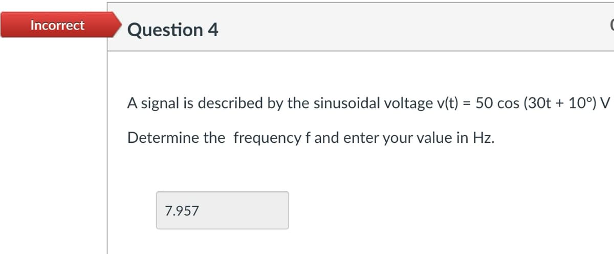
A signal is described by the sinusoidal voltage v(t) = 50 cos (30t + 10°) V Determine the frequency f and enter your value in Hz. 7.957
Q: B-6-15. Determine the values of K, T₁, and T2 of the system shown in Figure 1 so that the dominant…
A: Based on the image you sent, it appears to be a circuit diagram for a voltage regulator using a…
Q: Please answer in typing format
A:
Q: Given the following functions F(s), find f(t). (a) 8 +3 F (s) = Ꭶ s(s + 2)²
A:
Q: Please help I will like.....
A:
Q: Using the figure, if the frequency of V1 was 1.9 kHz and L1 was 10 mH, what would the reactance of…
A: Approach to solving the question:The reactance of an inductor is given as: X=j2πfL•So magnitude is:…
Q: A six-pole, lap-wound, 220 V, shunt-excited d.c. machine takes an armature current of 2.5 A when…
A: Step 1:Step 2:Step 3:Step 4:
Q: I had asked this question, but i am not sure if it got picked up, if you can solve this it would be…
A: Step 1Step 2 Step 3 Step 4
Q: None
A: Step 1:
Q: name three guidelines that should be followed when monitoring data?
A: for more information ping me happy learning
Q: Solve the following circuit for I, using Thevenin's Theorem. HH -31-52 |↓ 10 = ? ΙΩ √620° V 12 220°…
A: Step 1:
Q: I need an answer for this in less than 5 hours so could I please recieve an answer for this. I need…
A: Step 1:
Q: Please answer in typing format
A: In electrical installations, it's crucial to adhere to safety standards to prevent potential…
Q: Solve a to c handrwitten step by step solution by also showing the inverse z transform if necessary…
A: Step 1: Step 2: Step 3: Step 4: Step 5:
Q: Please answer in typing format
A: To plot \( V_{\text{out}} \) as a function of \( V_{\text{in}} \) for the given circuit using the…
Q: Please help with this parctice problem so I may study
A: based on your description of the circuit being a voltage regulator with a Zener diode and a BJT,…
Q: How do you find the current and the voltage of each resistor?
A: Step 1: Step 2: Step 3: Step 4:
Q: explain each step and show how to get to this answer please i do not undestand
A: The image you sent, it appears to be a circuit diagram with a voltage source (V1), resistors (R1,…
Q: 6.7 Draw the logic diagram of a four-bit register with four D flip- flops and four 4×1 multiplexers…
A: To draw the logic diagram of the four-bit register with four D flip-flops and four 4×1 multiplexers,…
Q: The switch in the circuit shown in Fig. P8.46 has been in position a for a long time. At t = 0, the…
A:
Q: Please answer in typing format
A: Sure, I can help you with this problem! The image you sent contains a word problem about analyzing a…
Q: please solve a to c detailed step by step solution thank you
A: Step 1: Step 2: Step 3: Step 4:
Q: Please answer in typing format
A: Step 1:Step 2:
Q: can u solve this in 20 min?
A: Step 1: Circuit diagram:Step 2:Step 3:Step 4:Step 5: Waveforms:a) Current:b) Voltage:
Q: Electrical plants Draw the connection diagram of the Impulse relay and write the working principle…
A: Working Principle:Initial State: In its initial state, an impulse relay's contacts are in one…
Q: Find the cross correlation Rxy between two signals x(t) = e−²tu(t) and y(t) = u(−t)
A:
Q: Please answer in typing format
A: Step 1: Step 2: Step 3:
Q: EXERCISE 14.3.9 (a) Find (t) fort > 0 in the circuit below. 10 V + t = 0 802 202 1/3 H io(1) ww 3/8…
A: Step 1: for t<0 for long time capacitor acts as open circuit and inductor acts as short circuit…
Q: Electrical Circuits / I need a correctly hand-drawn expert solution.
A: Step 1:Step 2:Step 3:Step 4:
Q: please solve only d with detailed step by step solution thank you
A: Step 1: Step 2:
Q: Find v0 if it is 20 V using source transformations.
A: Step 1: Step 2: Step 3: Step 4:
Q: (a) Find an expression for vo (t) fort > 0 in the circuit shown in Fig. 4 (a). 20 6 Ո 10 www www www…
A: Step 1: Step 2: Step 3: Step 4:
Q: The input signal x(n) = [ 1, 2, 3, -1, -2, -3, 4, 5, 6 Jis given to a system described by the…
A: Step 1: Step 2: Step 3: Step 4:
Q: The total inductance that I got is 2.4H, can you check if my answer is correct?
A: Step 1: As we can see 2 inductance of 4H are connected in parallel. so we get (4||4)=[(4*4)/(4+4)]…
Q: please solve this question a to c with handwritten detailed step by step solution thank you
A: Step 1: Step 2: Step 3: Step 4:Step 5:
Q: 9. Suppose we design an inverting amplifier using 5% tolerance resistors and an ideal op-amp. The…
A: To calculate the minimum and maximum possible gains and the percent tolerance of the gain for an…
Q: 2- If the following voltage signals applied to the corresponding elements, find the currents passing…
A:
Q: Please answer in typing format
A: Step 1:As given, the transformer has a Full Load (F.L.) efficiency of 98% at 0.8 power factorF.L.…
Q: The 50 mm radius pulley A of the clothes dryer rotates with an angular acceleration of α = (270¹²)…
A:
Q: I need an expert's solution for this question, and it should be comprehensive and accurate.
A: Approach to solving the question: Detailed explanation: Examples: Key references:
Q: Q3: A plant has a nominal model given by G(s) = 1 S(S+1)(1+2s) assume that this plant is to be…
A: Step 1: Step 2: IF YOU HAVE ANY DOUBT YOU CAN COMMENT HERE THANKS
Q: The charge on an electron is 1.6 x 10⁻¹⁹ coulombs. How many electrons must flow ina circuit to give…
A: Approach to solving the question:Please see attached photos for detailed solutions. Thank you.…
Q: The diagram below shows a capacitive circuit supplied by two different sources. Position 1: E1=15v…
A: Step 1: Step 2: Step 3: Step 4:Step 5:Step 6:Step 7:
Q: If V_1 = 2.34 V and V_2 = 4.33 V, how are these found using node-voltage analysis?
A:
Q: please solve a to c detailed step by step solution thank you
A: Step 1:(a)Direct Form I structure:In the direct form I structure, the system function is implemented…
Q: Can you check if my answers are correct (a) Determine the time constant of the circuit. T = 5.6ms…
A:
Q: Exercise 5 Find 11, 12 and ID2 in the circuit below. E 20 V 2 D1 Si ID2 R₁ R₂ D2 ▼ Si V₁ 3.3 ΚΩ 5.6…
A: Step 1: Basic concept Step 2: Solution page 1Step 3: Solution page 2
Q: 04. Write the necessary mesh equations for the circuit shown in Fig. Q10.04. E2 1/1/2 R2 w R3 www R1…
A: Step 1: Step 2: Step 3: Step 4:
Q: Mechanical Engineering: I need an expert solution provided in handwritten format with a clear and…
A:
Q: Q.4: Find the Laplace Transform £ {6e-21 [ ['t cos(-1) dt} 0
A: Step 1: Step 2: Step 3:
Q: Suppose X and Y have the following joint PDF: [√c²-u²-v², if u≥0, v≥0, u² + v² ≤c² fxy (u,v) = 0.…
A: Hope you got your answer, if any query then raise it.Kindly do rate this helpful.....Thank You
Step by step
Solved in 2 steps with 1 images
- Assume that the current flow through the resistor, IR, is 15 A; the current flow through the inductor, IL is 36 A; and the circuit has an apparent power of 10,803 VA. The frequency of the AC voltage is 60 Hz. ET ER EL IT IR15A IL36A Z R XL VA10,803 P VARSL PF LIt is given that v(t)=20 sin π|t|V over the interval –1≤t≤1 s. Thefunction then repeats itself. What is the fundamental frequency in radians per second?Homework: For the circuit shown Find the mathematical expression for the transient behaviour of the V C and ic if the capacitor was initially uncharged and the switch is closed at position 1 when 1. 2. 3. t = 0 sec. Find the mathematical expression for V C and ic if the switch is moved to position . 2att - 1 Plot the waveforms of the V C and i C obtained from the parts 1 to 3. i C; 10mu 4 mA R 1 * 5k * Omega C R 2; 1k * Omega; R 3 3 kΩ in the figure below:
- 12. 7.12 In the circuit , let Ig represent the dc current source, σrepresent the fraction of initial energy stored in the inductor that isdissipated in to seconds, and L represent the inductance. 1. a) Show thatR=Lln[1/(1−σ)]2tosolve the following Amplitude (A), period (T), and frequency (f) using the measurement shown in the picture: 1. Amplitude = (V/DIV) DIV = 2. period (T) = (T/DIV) DIV = 3. frequency= 1/T=Why is the following situation impossible? The LC circuit as shown has L = 30.0 μH and C = 50.0 μF. The capacitor has an initial charge of 200 μC. The switch is closed, and the circuit undergoes undamped LC oscillations. At periodic instants, the energies stored by the capacitor and the inductor are equal, with each of the two components storing 250 μJ.
- For t < 0, the capacitor in the given figure is completely discharged. Assume that the switch is thrown at t = 0. Let VS = 15 V, R = 200 Ω, L = 20 mH, and C = 0.1 μF.1. Find the equation defined by the waveform x(t) as shown in the figure below. evaluate x(t) using the integral from -∞ to ∞ of x(t)∂(t)dt and also evaluate x(t) at 1.5. Determine also the power content, energy content and plot the odd and even component. Answers should be in 8 decimal placesFind the impedance theoretically of a wire if it carries the frequency 10 kHz have a voltage is 8v, the current is 2mA, resistance is 12 kΩ , inductance 27 mH and capacitance 0.2 µf
- For the circuit shown, determine the energy stored in the inductor. The component values are VS = 11 V, R1 = 9 Ω, R2 = 4 Ω, R3 = 8 Ω, C = 0.161 F, L = 0.01Compute for the Energy and Power of the following signals in terms of per unit use the proper formula whether the signal is continuous or discrete. 2[cos(t) + isin(t)]An L-R-C series circuit has R = 60.0 Ω, L = 0.800 H, and C = 3.00 x 10⁻⁴ F. The ac source has voltage amplitude 90.0 V and angular frequency 120 rad/s. (a) What is the maximum energy stored in the inductor? (b) When the energy stored in the inductor is a maximum, how much energy is stored in the capacitor? (c) What is the maximum energy stored in the capacitor?