
Concept explainers
Videos
If the input impedance is defined as Zin = Vs/Is, find the input impedance of the op amp circuit in Fig. 10.116 when R1 = 10 kΩ, R2 = 20 kΩ, C1 = 10 nF, C2 = 20 nF, and ω = 5000 rad/s.
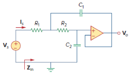
Figure 10.116
Calculate the input impedance
Answer to Problem 73P
The value of input impedance
Explanation of Solution
Given data:
Refer to Figure 10.116 in the textbook for the op amp circuit.
The values of resistance
The values of capacitance
The value of angular frequency
Formula used:
Write the expression to calculate impedance of the capacitor.
Here,
Write the formula for input impedance of the given op amp circuit.
Here,
Calculation:
Substitute
Substitute
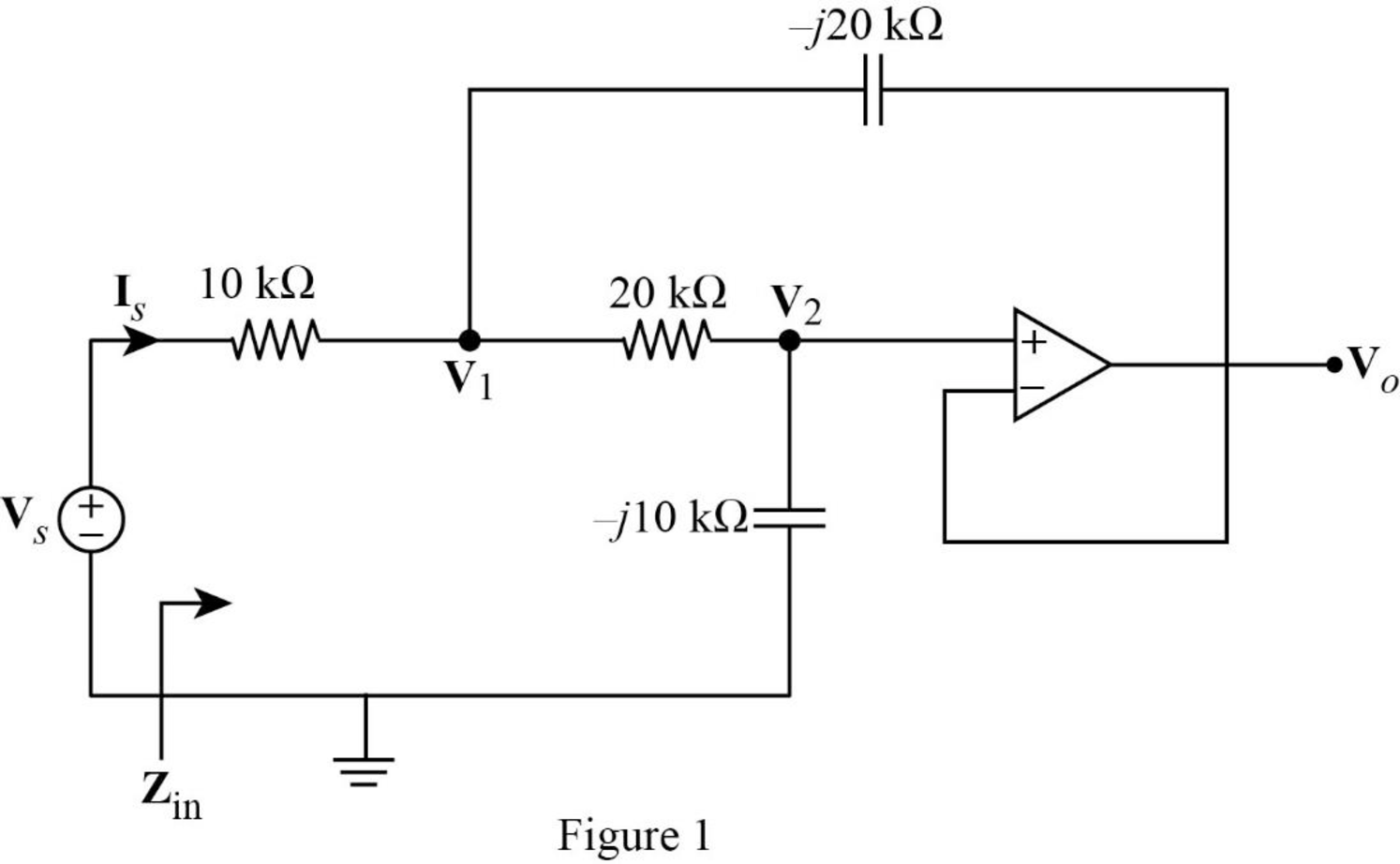
The frequency domain representation of given circuit with the node voltage is shown in Figure 1.
Apply Kirchhoff’s current law at node
According to the properties of an ideal op amp, the voltage appear across the input terminals of the op amp is zero.
The voltage at the inverting terminal will be appear at the non-inverting input terminal. Since the output voltage is fed back to the inverting terminal, the voltage
Substitute equation (4) in (3).
Reduce the equation as follows.
Apply Kirchhoff’s current law at node
Substitute equation (5) and (7).
Simplify the equation as follows.
Substitute equation (7) in (5).
Simplify the above equation as follows.
Substitute equation (8) in (7).
From Figure 1, write the expression for current
Substitute equation (10) in (2).
Conclusion:
Thus, the value of input impedance
Want to see more full solutions like this?
Chapter 10 Solutions
Fundamentals of Electric Circuits


- R1 6 kN R2 2 kn CFI µF Vout The value of the corner frequency in the circuit shown is.rad/s 220 O none of the above ) 666 O 700 O 100 O 415 Oarrow_forward3. Let Is= 50A, nd 20 40 10arrow_forwardProblem 10.073 - Input impedance of an Op Amp If the input impedance is defined as Zin = Vs/ls, find the input impedance of the op amp circuit given below when R₁ = 11 kQ2, R₂ = 20 kQ2, C₁ = 10 nF, C₂ = 20 nF, and @= 5000 rad/s. Please report your answer so the magnitude is positive and all angles are in the range of negative 180 degrees to positive 180 degrees. C₁ V₂ I₂ R₁ www + Zin The value of Zin = R₂ www C₂ 9 ΚΩ.arrow_forward
- 1. In a transistor amplifier how is a small ac signal defined? 2. Why are capacitors and voltage sources treated as short circuits when analyzing the ac operation of a transistor amplifier? 3. Draw the equivalent AC circuit of image number 3. (Note: no need to draw the hybrid equivalent model only the AC equivalent circuit) oVc R1 Rc C3 Vs RL R2 C2 r's REarrow_forward10.23. Draw the block diagrams of both the direct forms I and II simulation diagrams for the systems with the following difference equations: ey[n] - 1.8y[n 1] +0.9y[n - 3] = 2x[n] -3.5x[n 1] +2.8.x[n − 2] 1arrow_forwardobtain V0arrow_forward
- Assume that the voltage drop across the resistor, ER, is 78 V; the voltage drop across the capacitor, EC, is 104 V; and the circuit has a total impedance, Z, of 20 . The frequency of the AC voltage is 60 Hz. Find the missing values. ET ER78V EC104V IT IR IC Z20 R XC VA P VARSC PF Carrow_forwardDetermine if each statement is True or False; if false, please explain whya) A forced oscillator is when a system is being yelled at to perform a specific motion.b) Impedance is a measure of the total resistance a RLC series circuit has towards current.c) The phase angle tells us how “out-of-phase” the charge on the capacitor iswith the driving voltage.arrow_forwardФЫ В А П Р О ВАПРОЛДЗАПРОЛДЖЭ ЯЧСМИТНЧСМИТЬБНСМИТЬБЮ SOLVE STEP BY STEP IN DIGITAL FORMAT 100 cos (2 x 10⁴t+3°) V 89. Use superposition to determine the voltages vi(1) and v2(t) in the circuit of Figure 10.84. (1) 47 kn WWW mm 112 дн 56 кп :33 μF m 112 H 92 MF (1) 47 kn -т 100 cos (2x 10⁵t-3°) V ЙЦУКЕНГШУКЕНГШЩЗКЕНГШЩзхъarrow_forward
- For a given R-C series circuit that is supplied by a 120 VAC, 60 Hz supply, the impedance triangle shows Z = 100 Q and R = 40 Q. The capacitance of the circuit is: a) 28.9 uF K b) 34.6 HF c) 28.9 nF d) 2.89 µFarrow_forwardA CTFT has the value e T/4 at a frequency, f= 5. The value of that same CTFT at a frequency of f= -5 is A+j VB The numerical values of the constants are A= and B=arrow_forwardB- An amplifier system has NF 8 dB, when the input signal with SIN =8 dB calculate the SNR at the output of the amplifier systemarrow_forward
 Delmar's Standard Textbook Of ElectricityElectrical EngineeringISBN:9781337900348Author:Stephen L. HermanPublisher:Cengage Learning