
Mechanics of Materials, 7th Edition
7th Edition
ISBN: 9780073398235
Author: Ferdinand P. Beer, E. Russell Johnston Jr., John T. DeWolf, David F. Mazurek
Publisher: McGraw-Hill Education
expand_more
expand_more
format_list_bulleted
Videos
Textbook Question
Chapter 10.4, Problem 92P
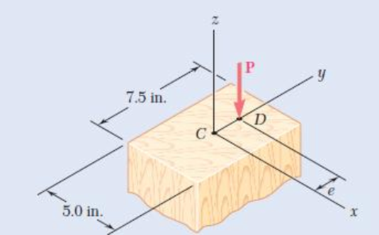
Solve Prob. 10.91 using the interaction method and an allowable stress in bending of 1300 psi.
10.91 A sawn-lumber column of 5.0 × 7.5-in. cross section has an effective length of 8.5 ft. The grade of wood used has an adjusted allowable stress for compression parallel to the grain σC = 1180 psi and an adjusted modulus E = 440 × 103 psi. Using the allowable-stress method, determine the largest eccentric load P that can be applied when (a) e = 0.5 in., (b) e = 1.0 in.
Fig. P10.91
Expert Solution & Answer
Want to see the full answer?
Check out a sample textbook solution
Students have asked these similar questions
7. Straight rods of 0.4ft diameter and 100ft length are
stored by coiling the rods inside a drum of 1.25ft in-
side diameter. Assuming that the yield strength is not
exceeded, determine the maximum stress in the coiled
rod, the corresponding bending moment in the rod. Use
E = 29 * 10°psi.
Each of the three rolled-steel beams shown (numbered 1, 2, and 3) is to carry a 64-kip load uniformly distributed over the beam. Each of these beams has a 12-ft span and is to be supported by the two 24-ft rolled-steel girders AC and BD. The allowable normal stress for the steel used is 22.5 ksi.
Determine the section modulus for each girder and select the most economical W shape for the two girders using the table given below. (Round the final answer to one decimal place.)
A rectangular column is made of a grade of sawn wood that has an adjusted allowable stress for compression parallel to the grain σC = 8.3 MPa and a modulus of elasticity E = 11.1 GPa. Using the allowable-stress method, determine the largest allowable effective length L that can be used. Take P = 88 kN. (Round the final answer to two decimal places.)
The largest allowable effective length L that can be used is m.
Chapter 10 Solutions
Mechanics of Materials, 7th Edition
Ch. 10.1 - Knowing that the spring at A is of constant k and...Ch. 10.1 - Two rigid bars AC and BC are connected by a pin at...Ch. 10.1 - 10.3 and 10.4 Two rigid bars AC and BC are...Ch. 10.1 - 10.3 and 10.4 Two rigid bars AC and BC are...Ch. 10.1 - The steel rod BC is attached to the rigid bar AB...Ch. 10.1 - The rigid rod AB is attached to a hinge at A and...Ch. 10.1 - The rigid bar AD is attached to two springs of...Ch. 10.1 - A frame consists of four L-shaped members...Ch. 10.1 - Determine the critical load of a pin-ended steel...Ch. 10.1 - Determine the critical load of a pin-ended wooden...
Ch. 10.1 - A column of effective length L can be made by...Ch. 10.1 - A compression member of 1.5-m effective length...Ch. 10.1 - Determine the radius of the round strut so that...Ch. 10.1 - Determine (a) the critical load for the square...Ch. 10.1 - A column with the cross section shown has a...Ch. 10.1 - A column is made from half of a W360 216...Ch. 10.1 - A column of 22-ft effective length is made by...Ch. 10.1 - A single compression member of 8.2-m effective...Ch. 10.1 - Knowing that P = 5.2 kN, determine the factor of...Ch. 10.1 - Members AB and CD are 30-mm-diameter steel rods,...Ch. 10.1 - The uniform brass bar AB has a rectangular cross...Ch. 10.1 - A 1-in.-square aluminum strut is maintained in the...Ch. 10.1 - A 1-in.-square aluminum strut is maintained in the...Ch. 10.1 - Column ABC has a uniform rectangular cross section...Ch. 10.1 - Column ABC has a uniform rectangular cross section...Ch. 10.1 - Column AB carries a centric load P of magnitude 15...Ch. 10.1 - Each of the five struts shown consists of a solid...Ch. 10.1 - A rigid block of mass m can be supported in each...Ch. 10.2 - An axial load P = 15 kN is applied at point D that...Ch. 10.2 - An axial load P is applied to the 32-mm-diameter...Ch. 10.2 - The line of action of the 310-kN axial load is...Ch. 10.2 - Prob. 32PCh. 10.2 - An axial load P is applied to the 32-mm-square...Ch. 10.2 - Prob. 34PCh. 10.2 - Prob. 35PCh. 10.2 - Prob. 36PCh. 10.2 - Solve Prob. 10.36, assuming that the axial load P...Ch. 10.2 - The line of action of the axial load P is parallel...Ch. 10.2 - Prob. 39PCh. 10.2 - Prob. 40PCh. 10.2 - The steel bar AB has a 3838-in. square cross...Ch. 10.2 - For the bar of Prob. 10.41, determine the required...Ch. 10.2 - A 3.5-m-long steel tube having the cross section...Ch. 10.2 - Prob. 44PCh. 10.2 - An axial load P is applied to the W8 28...Ch. 10.2 - Prob. 46PCh. 10.2 - A 100-kN axial load P is applied to the W150 18...Ch. 10.2 - A 26-kip axial load P is applied to a W6 12...Ch. 10.2 - Prob. 49PCh. 10.2 - Axial loads of magnitude P = 84 kN are applied...Ch. 10.2 - An axial load of magnitude P = 220 kN is applied...Ch. 10.2 - Prob. 52PCh. 10.2 - Prob. 53PCh. 10.2 - Prob. 54PCh. 10.2 - Axial loads of magnitude P = 175 kN are applied...Ch. 10.2 - Prob. 56PCh. 10.3 - Using allowable stress design, determine the...Ch. 10.3 - Prob. 58PCh. 10.3 - Prob. 59PCh. 10.3 - A column having a 3.5-m effective length is made...Ch. 10.3 - Prob. 61PCh. 10.3 - Bar AB is free at its end A and fixed at its base...Ch. 10.3 - Prob. 63PCh. 10.3 - Prob. 64PCh. 10.3 - A compression member of 8.2-ft effective length is...Ch. 10.3 - A compression member of 9-m effective length is...Ch. 10.3 - A column of 6.4-m effective length is obtained by...Ch. 10.3 - A column of 21-ft effective length is obtained by...Ch. 10.3 - Prob. 69PCh. 10.3 - Prob. 70PCh. 10.3 - Prob. 71PCh. 10.3 - Prob. 72PCh. 10.3 - Prob. 73PCh. 10.3 - For a rod made of aluminum alloy 2014-T6, select...Ch. 10.3 - Prob. 75PCh. 10.3 - Prob. 76PCh. 10.3 - A column of 4.6-m effective length must carry a...Ch. 10.3 - A column of 22.5-ft effective length must carry a...Ch. 10.3 - Prob. 79PCh. 10.3 - A centric load P must be supported by the steel...Ch. 10.3 - A square steel tube having the cross section shown...Ch. 10.3 - Prob. 82PCh. 10.3 - Prob. 83PCh. 10.3 - Two 89 64-mm angles are bolted together as shown...Ch. 10.3 - Prob. 85PCh. 10.3 - Prob. 86PCh. 10.3 - Prob. 87PCh. 10.3 - Prob. 88PCh. 10.4 - An eccentric load is applied at a point 22 mm from...Ch. 10.4 - Prob. 90PCh. 10.4 - Prob. 91PCh. 10.4 - Solve Prob. 10.91 using the interaction method and...Ch. 10.4 - A column of 5.5-m effective length is made of the...Ch. 10.4 - Prob. 94PCh. 10.4 - A steel compression member of 9-ft effective...Ch. 10.4 - Prob. 96PCh. 10.4 - Two L4 3 38-in. steel angles are welded together...Ch. 10.4 - Solve Prob. 10.97 using the interaction method...Ch. 10.4 - A rectangular column is made of a grade of sawn...Ch. 10.4 - Prob. 100PCh. 10.4 - Prob. 101PCh. 10.4 - Prob. 102PCh. 10.4 - Prob. 103PCh. 10.4 - Prob. 104PCh. 10.4 - A steel tube of 80-mm outer diameter is to carry a...Ch. 10.4 - Prob. 106PCh. 10.4 - Prob. 107PCh. 10.4 - Prob. 108PCh. 10.4 - Prob. 109PCh. 10.4 - Prob. 110PCh. 10.4 - Prob. 111PCh. 10.4 - Prob. 112PCh. 10.4 - Prob. 113PCh. 10.4 - Prob. 114PCh. 10.4 - Prob. 115PCh. 10.4 - A steel column of 7.2-m effective length is to...Ch. 10 - Determine (a) the critical load for the steel...Ch. 10 - Prob. 118RPCh. 10 - Prob. 119RPCh. 10 - (a) Considering only buckling in the plane of the...Ch. 10 - Member AB consists of a single C130 3 10.4 steel...Ch. 10 - The line of action of the 75-kip axial load is...Ch. 10 - Prob. 123RPCh. 10 - Prob. 124RPCh. 10 - A rectangular column with a 4.4-m effective length...Ch. 10 - Prob. 126RPCh. 10 - Prob. 127RPCh. 10 - Prob. 128RP
Knowledge Booster


Learn more about
Need a deep-dive on the concept behind this application? Look no further. Learn more about this topic, mechanical-engineering and related others by exploring similar questions and additional content below.Similar questions
- 7. A constructed beam ACB has a cross section of 1.5in X 1.5 in supported by a column CE having a cross section of 1in X 1in. Assuming that the allowable stresses for the connecting bolt for point C is 24 ksi for shearing and 30 ksi for bearing, determine the minimum diameter of the bolt required in Inches. 10 3A 3tarrow_forward. The cast-iron frame of a small press is shaped as shown below on the left. The cross section a-a of the frame is shown on the right. For a load P of 20 kip, determine (a) the axial load and bending moment at cross section a-a, and (b) the maximum tensile and compressive stresses on cross section a-a. P Pl 17 in a- - a 2 in 8 in 8 in 5 in 2 in 5 inarrow_forwardTo analyze a beam subjected to a vertical force and a triangular distributed load, determine the reaction forces acting on each of the supports, determine the minimum pin diameter for one support subjected to single shear, and determine the average shear stress in a pin support subjected to double shear. As shown, beam BC is subjected to a load of magnitude P= 780.0 kN and a triangular distributed load of w = 510.0 kN/m. The support rod AB is oriented at an angle of θ = 150.0 ∘ from the beam. Let a = 4.000 m and b = 13.00 m . Cross-sectional views are shown for B and C. 1) Part A: Determine the reaction force at B. 2) Part B: Determine the reaction force at C. 3) Part C: If the average shear stress in the material is not to exceed τavg = 150.0 MPa, determine the minimum required diameter for the pin at B. 4) Part D: If the diameter of the pin is d = 125.0 mm, what is the average shear stress in the pin at C.arrow_forward
- To analyze a beam subjected to a vertical force and a triangular distributed load, determine the reaction forces acting on each of the supports, determine the minimum pin diameter for one support subjected to single shear, and determine the average shear stress in a pin support subjected to double shear. As shown, beam BC is subjected to a load of magnitude P = 780.0 kN and a triangular distributed load of w = 510.0 kN/m. The support rod AB is oriented at an angle of θ = 150.0 ∘ from the beam. Let a = 4.000 m and b = 13.00 m . Cross-sectional views are shown for B and C. Determine the reaction force at B. Determine the reaction force at C. If the average shear stress in the material is not to exceed τavg = 150.0 MPa , determine the minimum required diameter for the pin at B. If the diameter of the pin is d = 125.0 mm, what is the average shear stress in the pin at C.arrow_forwardThe piston of an automobile engine is held to the connecting rod by a wrist pin having an external diameter of 20 mm and internal diameter of 11 mm. The length of the bearing in the rod end is 25 mm and the bearing in each boss of the piston is 15 mm. The maximum load transmitted is 14.50 kN. (a) Determine the bearing pressure between the rod end and the wrist pin. (b) Compare the maximum bending stress in the pin, assuming that it is a simple beam with a uniform load. Please solve completely ?arrow_forwardA rectangular column is made of a grade of sawn wood that has an adjusted allowable stress for compression parallel to the grain oc = 8.3 MPa and a modulus of elasticity E= 11.1 GPa. Using the allowable-stress method, determine the largest allowable effective length L that can be used. Take P= 105 kN. (Round the final answer to two decimal places.) 180 mm 240 mm D y 25 mm The largest allowable effective length L that can be used is 4.81 m.arrow_forward
- 4. A cover-plate beam is made up of a W21x147 section with 300 mm x 12 mm plates attached to the top and bottom flanges and is fastened by two rows of 20 mm rivets. The beam is simply supported over a span of 6m and carries a uniformly distributed load of 270 kN/m including its own weight. The shear capacity of each rivet is 30 kN. a. Determine the distance from the centroid of the cover plate to the neutral axis of the built-up section. b. Determine the moment of inertia of the built-up section about its neutral axis. c. Determine the longitudinal pitch of the rivets. Properties of W21x147 Overall depth, d= 560 mm Moment of Inertia, I = 0.00151 mm4 flange d. web W21x147arrow_forwardProblem 8.12 A bar of rectangular cross-section, with a width of 60 mm and a thickness of 40 mm, is bent in the shape of a horse shoe having a mean radius of 70 mm. Two equal and opposite forces of 10 kN each are applied at a distance of 12 cm from the centre line of the middle section so that they tend to straighten the rod. Find the maximum ten- sile and compressive stresses and construct a diagram showing the vari- ation of the normal stresses over the central section.arrow_forwardA lightweight lever consists of a 0.8m solid bar rigidly mounted to a large structure and a 0.5m solid lever welded to the solid bar. Using the loading indicated and assuming the material has a Young's Modulus of 200 GPa and a shear modulus of 86 GPa, calculate: (a) the maximum stress at Point A on the Cross-section a-a, (b) the vertical displacement of the knob when the load is applied relative to Cross-section a-a. B C 50 mm Section ad a 0.8 m 0.5 m 100 N 38 mm Focusarrow_forward
- Problem 17.3 The assembly consists of two A-36 steel rods and a rigid beam BD (meaning that BD does not deform/deflect compared with the elongation of the rods). Each rod has a diameter of 0.75 inches. If a force of 10 kips is applied to the bar as shown, determine the vertical displacement of the load. 3 ft 2 ft B E -1.25 ft- 0.75 ft 1 ft 10 kiparrow_forwardA 9 m beam simply supported at the ends carries a concentrated load of 10 kN at midspan. Select the lightest W section that can be employed using an allowable stress of 240 MPa. Determine the maximum stress of the selected beam.arrow_forwardA timber column, 8in. by 8in. in cross section is reinforced on all four sides by steel plates, each plate being 8in. wide and "t"in. thick. Determine the smallest value of "t" for which the column can support an axial load of 300 kips if the working stresses are 1200psi for timber and 20ksi for steel. The moduli of elasticity are 1.5x10^6psi for timber and 29x10^6psi foe steel -Draw and label the diagram correctly, No diagram in the solution will be marked wrong. -Shortcut solution will be marked wrong.- Direction of the assumption of the equilibrium equation must be shown, no direction will be marked wrong.arrow_forward
arrow_back_ios
SEE MORE QUESTIONS
arrow_forward_ios
Recommended textbooks for you
 Elements Of ElectromagneticsMechanical EngineeringISBN:9780190698614Author:Sadiku, Matthew N. O.Publisher:Oxford University Press
 Mechanics of Materials (10th Edition)Mechanical EngineeringISBN:9780134319650Author:Russell C. HibbelerPublisher:PEARSON
 Thermodynamics: An Engineering ApproachMechanical EngineeringISBN:9781259822674Author:Yunus A. Cengel Dr., Michael A. BolesPublisher:McGraw-Hill Education
 Control Systems EngineeringMechanical EngineeringISBN:9781118170519Author:Norman S. NisePublisher:WILEY
 Mechanics of Materials (MindTap Course List)Mechanical EngineeringISBN:9781337093347Author:Barry J. Goodno, James M. GerePublisher:Cengage Learning
 Engineering Mechanics: StaticsMechanical EngineeringISBN:9781118807330Author:James L. Meriam, L. G. Kraige, J. N. BoltonPublisher:WILEY
Elements Of Electromagnetics
Mechanical Engineering
ISBN:9780190698614
Author:Sadiku, Matthew N. O.
Publisher:Oxford University Press
Mechanics of Materials (10th Edition)
Mechanical Engineering
ISBN:9780134319650
Author:Russell C. Hibbeler
Publisher:PEARSON
Thermodynamics: An Engineering Approach
Mechanical Engineering
ISBN:9781259822674
Author:Yunus A. Cengel Dr., Michael A. Boles
Publisher:McGraw-Hill Education
Control Systems Engineering
Mechanical Engineering
ISBN:9781118170519
Author:Norman S. Nise
Publisher:WILEY
Mechanics of Materials (MindTap Course List)
Mechanical Engineering
ISBN:9781337093347
Author:Barry J. Goodno, James M. Gere
Publisher:Cengage Learning
Engineering Mechanics: Statics
Mechanical Engineering
ISBN:9781118807330
Author:James L. Meriam, L. G. Kraige, J. N. Bolton
Publisher:WILEY
Mechanics of Materials Lecture: Beam Design; Author: UWMC Engineering;https://www.youtube.com/watch?v=-wVs5pvQPm4;License: Standard Youtube License