
Concept explainers
Videos
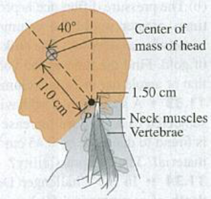
BIO Neck Muscles. A student bends her head at 40.0° from the vertical while intently reading her physics book, pivoting the head around the upper vertebra (point P in Fig. E11.23). Her head has a mass of 4.50 kg (which is typical), and its center of mass is 11.0 cm from the pivot point P. Her neck muscles are 1.50 cm from point P, as measured perpendicular to these muscles. The neck itself and the vertebrae are held vertical. (a) Draw a free-body diagram of the student’s head. (b) Find the tension in her neck muscles.
Figure E11.23
Want to see the full answer?
Check out a sample textbook solution
Chapter 11 Solutions
University Physics (14th Edition)
Additional Science Textbook Solutions
College Physics
University Physics with Modern Physics (14th Edition)
Sears And Zemansky's University Physics With Modern Physics
Cosmic Perspective Fundamentals
College Physics: A Strategic Approach (4th Edition)
Essential University Physics: Volume 1 (3rd Edition)


- A uniform beam resting on two pivots has a length L = 6.00 m and mass M = 90.0 kg. The pivot under the left end exerts a normal force n1 on the beam, and the second pivot located a distance = 4.00 m from the left end exerts a normal force n2. A woman of mass m = 55.0 kg steps onto the left end of the beam and begins walking to the right as in Figure P10.28. The goal is to find the womans position when the beam begins to tip. (a) What is the appropriate analysis model for the beam before it begins to tip? (b) Sketch a force diagram for the beam, labeling the gravitational and normal forces acting on the beam and placing the woman a distance x to the right of the first pivot, which is the origin. (c) Where is the woman when the normal force n1 is the greatest? (d) What is n1 when the beam is about to tip? (e) Use Equation 10.27 to find the value of n2 when the beam is about to tip. (f) Using the result of part (d) and Equation 10.28, with torques computed around the second pivot, find the womans position x when the beam is about to tip. (g) Check the answer to part (e) by computing torques around the first pivot point. Figure P10.28arrow_forwardA bridge of length 50.0 m and mass 8.00 104 kg is supported on a smooth pier at each end as shown in Figure P12.25. A truck of mass 3.00 104 kg is located 15.0 m from one end. What are the forces on the bridge at the points of support? Figure P12.25arrow_forwardA 10.0-kg monkey climbs a uniform ladder with weight 1.20 102 N and length L = 3.00 m as shown in Figure P12.14. The ladder rests against the wall and makes an angle of = 60.0 with the ground. The upper and lower ends of the ladder rest on frictionless surfaces. The lower end is connected to the wall by a horizontal rope that is frayed and can support a maximum tension of only 80.0 N. (a) Draw a force diagram for the ladder. (b) Find the normal force exerted on the bottom of the ladder. (c) Find the tension in the rope when the monkey is two-thirds of the way up the ladder. (d) Find the maximum distance d that the monkey can climb up the ladder before the rope breaks. (e) If the horizontal surface were rough and the rope were removed, how would your analysis of the problem change? What other information would you need to answer parts (c) and (d)? Figure P12.14arrow_forward
- A stepladder of negligible weight is constructed as shown in Figure P10.73, with AC = BC = ℓ. A painter of mass m stands on the ladder a distance d from the bottom. Assuming the floor is frictionless, find (a) the tension in the horizontal bar DE connecting the two halves of the ladder, (b) the normal forces at A and B, and (c) the components of the reaction force at the single hinge C that the left half of the ladder exerts on the right half. Suggestion: Treat the ladder as a single object, but also treat each half of the ladder separately. Figure P10.73 Problems 73 and 74.arrow_forwardIn Figure P10.40, the hanging object has a mass of m1 = 0.420 kg; the sliding block has a mass of m2 = 0.850 kg; and the pulley is a hollow cylinder with a mass of M = 0.350 kg, an inner radius of R1 = 0.020 0 m, and an outer radius of R2 = 0.030 0 m. Assume the mass of the spokes is negligible. The coefficient of kinetic friction between the block and the horizontal surface is k = 0.250. The pulley turns without friction on its axle. The light cord does not stretch and does not slip on the pulley. The block has a velocity of vi = 0.820 m/s toward the pulley when it passes a reference point on the table. (a) Use energy methods to predict its speed after it has moved to a second point, 0.700 m away. (b) Find the angular speed of the pulley at the same moment. Figure P10.40arrow_forwardA stepladder of negligible weight is constructed as shown in Figure P10.73, with AC = BC = = 4.00 m. A painter of mass m = 70.0 kg stands on the ladder d = 3.00 m from the bottom. Assuming the floor is frictionless, find (a) the tension in the horizontal bar DE connecting the two halves of the ladder, (b) the normal forces at A and B, and (c) the components of the reaction force at the single hinge C that the left half of the ladder exerts on the right half. Suggestion: Treat the ladder as a single object, but also treat each half of the ladder separately.arrow_forward
- Find the net torque on the wheel in Figure P10.23 about the axle through O, taking a = 10.0 cm and b = 25.0 cm. Figure P10.23arrow_forwardWhen you bend over, a series of large muscles, the erector spinae, pull on your spine to hold you up. Figure shows a simplified model of the spine as a rod of length L that pivots at its lower end. In this model, the center of gravity of the 320 N weight of the upper torso is at the center of the spine. The 160 N weight of the head and arms acts at the top of the spine. The erector spinae muscles are modeled as a single muscle that acts at an 12° angle to the spine. Suppose the person shown bends over to an angle of 30° from the horizontal. a. What is the tension in the erector muscle? Hint: Align your x-axis with the axis of the spine.b. A force from the pelvic girdle acts on the base of the spine. What is the component of this force in the direction of the spine? (This large force is the cause of many back injuries).arrow_forward11.52 · A Truck on a Drawbridge. A loaded cement mixer drives onto an old drawbridge, where it stalls with its center of gravity three-quarters of the way across the span. The truck driver radios for help, sets the handbrake, and waits. Meanwhile, a boat approaches, so the drawbridge is raised by means of a cable attached to the end opposite the hinge (Fig. P11.52). The draw- bridge is 40.0 m long and has a mass of 18,000 kg; its center of gravity is at its midpoint. The cement mixer, with driver, has mass 30,000 kg. When the drawbridge has been raised to an angle of 30° above the horizontal, the cable makes an angle of 70° with the surface of the bridge. (a) What is the tension T in the cable when the drawbridge is held in this position? (b) What are the horizontal and vertical components of the force the hinge exerts on the span? Figure P11.52 70° k100 m 40.0 m 30arrow_forward
 College PhysicsPhysicsISBN:9781285737027Author:Raymond A. Serway, Chris VuillePublisher:Cengage Learning
 Physics for Scientists and Engineers: Foundations...PhysicsISBN:9781133939146Author:Katz, Debora M.Publisher:Cengage Learning
 Principles of Physics: A Calculus-Based TextPhysicsISBN:9781133104261Author:Raymond A. Serway, John W. JewettPublisher:Cengage Learning
 Physics for Scientists and EngineersPhysicsISBN:9781337553278Author:Raymond A. Serway, John W. JewettPublisher:Cengage Learning
 Physics for Scientists and Engineers with Modern ...PhysicsISBN:9781337553292Author:Raymond A. Serway, John W. JewettPublisher:Cengage Learning