
Videos
(a)
Design a circuit which produces a transfer function of
(a)
Explanation of Solution
Problem design:
Synthesize a circuit that will yield the transfer function
Calculation:
The transfer function of the circuit is,
The above equation is written as,
For the above transfer function, it has two repeated zeros at
The Figure 14.39 (b) in the textbook, that shows a cascade two stages of the circuit with a zero at
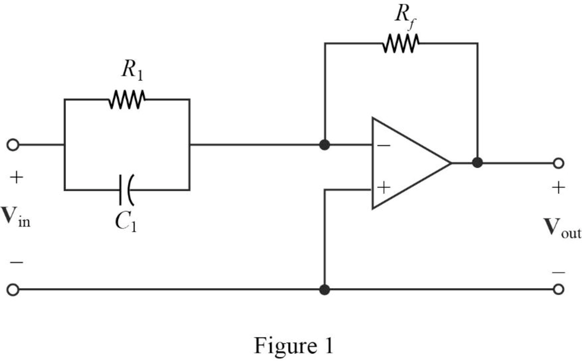
For a single zero,
Substitute
Let arbitrarily consider
Substitute
Transfer function:
The input impedance of the cascaded circuit is,
Then, write the Formula for the transfer function for the cascaded two stage amplifier.
Substitute
Thus, consider that the transfer function for
Substitute 1 for
Completing the design by letting
Since, two repeated zeros at
Therefore,
Substitute
Thus, the final design of the circuit is,
Conclusion:
Thus, a circuit is designed which produces a transfer function of
(b)
Design a circuit which produces a transfer function of
(b)
Explanation of Solution
Problem design:
Synthesize a circuit that will yield the transfer function
Calculation:
The transfer function of the circuit is,
Consider the transfer function for the cascaded circuit as below.
The above transfer function, it has two poles at
The Figure 14.39 (a) in the textbook, that shows a cascade two stages of the circuit with pole at
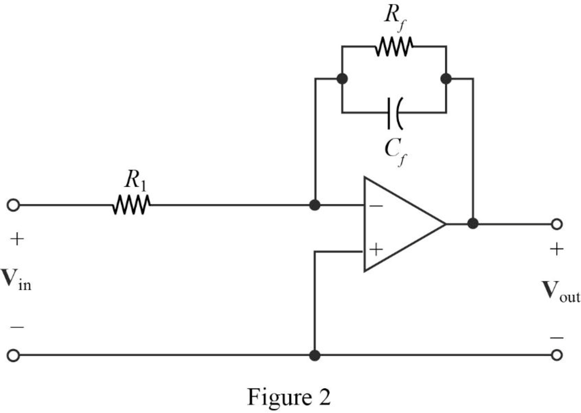
The above Figure 2, is the representation for the first stage and second stage of a cascaded circuit to be drawn.
Consider the denominator of given transfer function and the first pole as
Where,
Substitute
Let arbitrarily consider
Substitute
Transfer function:
Find the feedback impedance of the cascaded circuit in Figure 2.
Write the formula for the transfer function of the cascaded circuit in Figure 2 as follows
Substitute
Therefore, consider the transfer function for the first pole
Substitute 500 for
Completing the design by letting
Consider the denominator of given transfer function and the first pole as
Where,
Substitute
Arbitrarily consider
Substitute
Therefore, consider the transfer function for the second pole
Substitute 100 for
Completing the design by letting
Then, from the transfer function of the two stages write the complete transfer function as follows.
Substitute
Thus, the final design of the circuit is,
Conclusion:
Thus, a circuit is designed which produces a transfer function of
Want to see more full solutions like this?
Chapter 14 Solutions
Loose Leaf for Engineering Circuit Analysis Format: Loose-leaf


- Crossover/damped vs. damping ratio A second order system is define as: 1.3000 1.2000 R(s) k C(s) 1.1000 s(s + 23wn) 1.0000 0.9000 k 0.8000 1) What is the closed loop transfer function? 0.7000 0.0 0.2 0.4 0.6 0.8 1.0 2) What is the open loop transfer function? Phase Margin vs. damping ratio 90.0 80.0 1007 3) Using the open-loop transfer function, derive an equation for the ratio w/w. where c indicates the unity gain crossover frequency and d indicates the damped natural frequency. Plot the results for a damping ratio of 0 to .9 70.0 60.0 50.0 40.0 30.0 4) Using the open-loop transfer function, derive an equation for the phase margin at the crossover frequency. Plot the results for a damping ratio of 0 to .9 20.0 10.0 0.0 0.0 0.2 0.4 0.4 0.6 0.8 1.0arrow_forwardIdentify the correct transfer function H (s) = + V₁ V₂ of the circuit shown in the figure.arrow_forward2s-0.45 14, The system, having its transfer function H(s) = is considered as: A. Marginally Stable B. Stable C. Unstable D. Stability cannot be defined 8. | 4arrow_forward
- Classify the response of the system and write ihe transfer function of the step response: (t) = A+ Be 161 cos(12t + p) %3Darrow_forwardA system transfer function is given as: What is the DC gain of the system H(s) = 250 0.01(s+50)arrow_forwardösalg äbäi the open - loop transfer function of the system given as in figure below, what is error steady state * for an input r(t)=1+4t+3t^2 10 (s+1) G(s)= s²(5s+6) 3.6 O 5.6 7.6 O 10.6 Oarrow_forward
- Given the circuit below, with R=2 ohms and C=0.2 Farads, compute for the transfer function Vo(s)/Vin(s). Express your answers in 2 decimal places. Vin (t) i(t) vo(t) R Fill in the blanks the numerical coefficients to the TF shown below that corresponds to A , & D V.(8) Vin (s) As+Bs Cs+Ds+1 B.arrow_forward2. Consider the following transfer function model W(s) = 1 s5 +10s +35³ +50s² +24s +11 Use the Hurwitz criterion to determine if the closed-loop system is stable: W(s)arrow_forward2. (a) Derive the expression for vout(t) in terms of vin(t), or (b) Derive the transfer function T(s) = Vout(s)/Vin(s). R1 ideal R2 vout vin R3arrow_forward
- Given the following circuit. Assume that Ri = 2MW, Ro= 10MW, RL= 1MW, Ci =50nF, Co=40pF and beta b=200. Please help me to solve the following questions.a) Derive the Transfer Function for your circuit { H(s)=Vout(s)/Vin(s) }b) Substitute the numerical values and express the Transfer Function numericallyarrow_forwardDetermine a) The transfer function H(s) = Vo(s) / lo(s) for the circuit shown below b) Find the zeroes and the poles of this transfer function. T, (s) www. 3s Vo(s)arrow_forwardConsider the transfer function G(s) 5 s² +as+5 Select the answer closest to the value a for which the step response will have a rise time (within 30%) of .2 seconds. (a) 6.4 (b) 4.4 (c) 2.1 = (d) 1.05 (e) None of the above/ Specification cannot be satisfiedarrow_forward
 Introductory Circuit Analysis (13th Edition)Electrical EngineeringISBN:9780133923605Author:Robert L. BoylestadPublisher:PEARSON
 Delmar's Standard Textbook Of ElectricityElectrical EngineeringISBN:9781337900348Author:Stephen L. HermanPublisher:Cengage Learning
 Programmable Logic ControllersElectrical EngineeringISBN:9780073373843Author:Frank D. PetruzellaPublisher:McGraw-Hill Education
 Fundamentals of Electric CircuitsElectrical EngineeringISBN:9780078028229Author:Charles K Alexander, Matthew SadikuPublisher:McGraw-Hill Education
 Electric Circuits. (11th Edition)Electrical EngineeringISBN:9780134746968Author:James W. Nilsson, Susan RiedelPublisher:PEARSON
 Engineering ElectromagneticsElectrical EngineeringISBN:9780078028151Author:Hayt, William H. (william Hart), Jr, BUCK, John A.Publisher:Mcgraw-hill Education,