
Electronics Fundamentals: Circuits, Devices & Applications
8th Edition
ISBN: 9780135072950
Author: Thomas L. Floyd, David Buchla
Publisher: Prentice Hall
expand_more
expand_more
format_list_bulleted
Concept explainers
Videos
Textbook Question
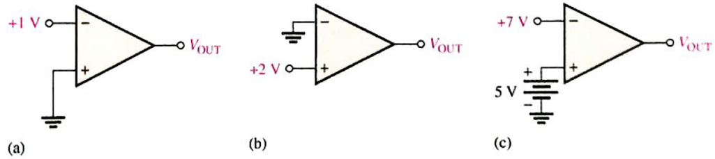
Chapter 19, Problem 1P
Determine the output level (maximum positive or maximum negative) for each comparator in Figure 19-59.
Expert Solution & Answer
Want to see the full answer?
Check out a sample textbook solution
Students have asked these similar questions
An integrator has a break frequency of 1
kHz and a unity gain frequency of 10 kHz.
Over what frequency range would the
circuit integrate a function and increase
the signal?
O 10 kHz only
O1 kHz and below
O 10 kHz and above
O 1 kHz to 10 kHz
In a flash A/D converter, the priority
* encoder is used to
select the first input O
select the highest value input
select the lowest value input O
select the last input O
For the given circuit, what is the minimum peak value of the output waveform if the input waveform is 10V square wave with switching time of 1 second?
Assume that the input switches between +10V and -10V DC levels.
O ov
O -5V
O - 20V
O -10V
Chapter 19 Solutions
Electronics Fundamentals: Circuits, Devices & Applications
Ch. 19 - A comparator will have a positive output whenever...Ch. 19 - Prob. 2TFQCh. 19 - Prob. 3TFQCh. 19 - Prob. 4TFQCh. 19 - Prob. 5TFQCh. 19 - The output of a Wien-bridge oscillator is a...Ch. 19 - A Wien-bridge oscillator uses both positive and...Ch. 19 - A two-pole filter has a maximum roll-off rate of...Ch. 19 - Prob. 9TFQCh. 19 - Prob. 10TFQ
Ch. 19 - Prob. 1STCh. 19 - To use a comparator for zero-level detection, the...Ch. 19 - Prob. 3STCh. 19 - Prob. 4STCh. 19 - The gain of the amplifier in Question 4 is -1 -2.2...Ch. 19 - To convert a summing amplifier to an averaging...Ch. 19 - Prob. 7STCh. 19 - Prob. 8STCh. 19 - The feedback path in an op-amp differentiator...Ch. 19 - Prob. 10STCh. 19 - Prob. 11STCh. 19 - Prob. 12STCh. 19 - Determine the output level (maximum positive or...Ch. 19 - A certain op-amp has open-loop gain of 80,000. The...Ch. 19 - Prob. 3PCh. 19 - Determine the output voltage for each circuit in...Ch. 19 - Determine the following in Figure 19—62: VR1 and...Ch. 19 - Find the value of Rf necessary to produce an...Ch. 19 - Find the output voltage when the input voltages...Ch. 19 - Determine the values of the input resistors...Ch. 19 - Determine the rate of change of the output voltage...Ch. 19 - A triangular waveform is applied to the input of...Ch. 19 - Prob. 11PCh. 19 - Calculate the resonant frequency of a lead-lag...Ch. 19 - Determine the JFET drain-to-source resistance in...Ch. 19 - Explain the purpose of D1 in Figure 19-66.Ch. 19 - Find the frequency of oscillation for the...Ch. 19 - What type of signal does the circuit in Figure...Ch. 19 - Prob. 17PCh. 19 - Determine the number of poles in each active...Ch. 19 - Calculate the critical frequencies for the filters...Ch. 19 - Determine the bandwidth and center frequency of...Ch. 19 - Determine the output voltage for the series...Ch. 19 - If R3 in figure 19-70 is doubled, what happens to...Ch. 19 - Prob. 23PCh. 19 - A series voltage regulator with constant-current...Ch. 19 - If R4 (determined in Problem 24) is halved, what...Ch. 19 - In the shunt regulator of Figure 19-72, when the...Ch. 19 - Assume that IL remains constant and VIN increases...Ch. 19 - Open file P19-29; files are found at...Ch. 19 - Open file P19-30 and determine if there is a...
Knowledge Booster


Learn more about
Need a deep-dive on the concept behind this application? Look no further. Learn more about this topic, electrical-engineering and related others by exploring similar questions and additional content below.Similar questions
- Draw the necessary waveforms. Inverting op-amp Re +10V Ri Vo Square Wave 741 Vị -10V GNDarrow_forwardFor the given circuit, what is the minimum peak value of the output waveform if the input waveform is 10V square wave with switching time of 1 second? Assume that the input switches between +10V and -10V DC levels. O V -5 V -10 V -20 Varrow_forwardFor the given circuit, what is the minimum peak value of the output waveform if the input waveform is 10V square wave with switching time of 1 second? Assume that the input switches between +10V and -10V DC levels. O - 10 V O - 20 V O ov O -5 Varrow_forward
- design a triangular wave oscillator with oscillation frequency of (50 KHz) andtriangle wave has Vp-p = 6v with Vcc= 18v draw circuit and output waves (vo1 andVo2)arrow_forwardhil E 3. Identify the type of input mode for each op-amp in Figure 12-61. Val Figure 12-61 4. A certain op-amp has a CMRR of 250,000. Convert this to decibels. ▸arrow_forwardIn what region the following circuit will be in? +1.8 V o VD O a. Triode O b. None- off the options O c. Saturation O d. Cut-offarrow_forward
- If the feedback resistor in an non-inverting opamp is open, the voltage gain increases decreases is not affected depends on Riarrow_forwardRy= 100ka C= OL047pF RI 10kO 15V R2 10k2, 1. Mention the phase difference between the input and output waveforms? 2. Calculate the Vout of the output waveforms? 3. Calculate the comer frequency of output waveform? 4. Draw the input and output waveforms of integrator.arrow_forwardIn an opamp when the input voltage exceeds a specified reference voltage, the output changes state.arrow_forward
- What is the output signal voltage for a gain of 20 and input voltage of 30mV? O 600mV O 6V O 60mV O 600Varrow_forwardAlthough current is blocked in reverse bias, (a) there is some current due to majority carriers (b) there is a very small current due to minority carriers (c) there is an avalanche currentarrow_forwardto go Determine the output level (maximum positive or maximum negative) for each comparator in Figure 1. Search IF (b) 6 SV (c)arrow_forward
arrow_back_ios
SEE MORE QUESTIONS
arrow_forward_ios
Recommended textbooks for you
 Introductory Circuit Analysis (13th Edition)Electrical EngineeringISBN:9780133923605Author:Robert L. BoylestadPublisher:PEARSON
 Delmar's Standard Textbook Of ElectricityElectrical EngineeringISBN:9781337900348Author:Stephen L. HermanPublisher:Cengage Learning
 Programmable Logic ControllersElectrical EngineeringISBN:9780073373843Author:Frank D. PetruzellaPublisher:McGraw-Hill Education
 Fundamentals of Electric CircuitsElectrical EngineeringISBN:9780078028229Author:Charles K Alexander, Matthew SadikuPublisher:McGraw-Hill Education
 Electric Circuits. (11th Edition)Electrical EngineeringISBN:9780134746968Author:James W. Nilsson, Susan RiedelPublisher:PEARSON
 Engineering ElectromagneticsElectrical EngineeringISBN:9780078028151Author:Hayt, William H. (william Hart), Jr, BUCK, John A.Publisher:Mcgraw-hill Education,
Introductory Circuit Analysis (13th Edition)
Electrical Engineering
ISBN:9780133923605
Author:Robert L. Boylestad
Publisher:PEARSON
Delmar's Standard Textbook Of Electricity
Electrical Engineering
ISBN:9781337900348
Author:Stephen L. Herman
Publisher:Cengage Learning
Programmable Logic Controllers
Electrical Engineering
ISBN:9780073373843
Author:Frank D. Petruzella
Publisher:McGraw-Hill Education
Fundamentals of Electric Circuits
Electrical Engineering
ISBN:9780078028229
Author:Charles K Alexander, Matthew Sadiku
Publisher:McGraw-Hill Education
Electric Circuits. (11th Edition)
Electrical Engineering
ISBN:9780134746968
Author:James W. Nilsson, Susan Riedel
Publisher:PEARSON
Engineering Electromagnetics
Electrical Engineering
ISBN:9780078028151
Author:Hayt, William H. (william Hart), Jr, BUCK, John A.
Publisher:Mcgraw-hill Education,
Differential Amplifiers Made Easy; Author: The AudioPhool;https://www.youtube.com/watch?v=Mcxpn2HMgtU;License: Standard Youtube License