
Concept explainers
Videos
A comparator will have a positive output whenever the noninverting input is greater than the inverting input.
Whether the given statement is true or false.
Answer to Problem 1TFQ
The statement is true.
Explanation of Solution
Given:
When the value of the non-inverting terminal is greater than the inverting terminal than the comparator will have a positive output.
The circuit diagram of the op-amp is:
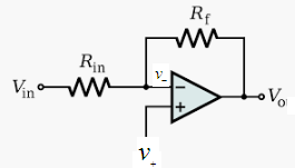
The output is given as:
Now, when the value of the non-inverting input is greater than the inverting input than the output of the comparator op-amp is positive.
Similarly, when the non-inverting terminal is less than the inverting terminal then the output will be negative:
Therefore, the given statement is true that the comparator output will be positive if the value of the non-inverting terminal is greater than the inverting terminal.
Want to see more full solutions like this?
Chapter 19 Solutions
Electronics Fundamentals: Circuits, Devices & Applications


- For the given circuit, what is the minimum peak value of the output waveform if the input waveform is 10V square wave with switching time of 1 second? Assume that the input switches between +10V and -10V DC levels. O - 10 V O - 20 V O ov O -5 Varrow_forwardThe input signal in figure shown below is applied to the comparator in the figure. Draw the output signal showing its proper relationship to the input signal. Assume the maximum output levels of the comparator are (+/-)14 V. A Vin 0- 5 V- -5 V- +15 V R₁ 8.2 ΚΩ R₂ 1.0 ΚΩ 550 www V outarrow_forwardFor the given circuit, what is the minimum peak value of the output waveform if the input waveform is 10V square wave with switching time of 1 second? Assume that the input switches between +10V and -10V DC levels. O V -5 V -10 V -20 Varrow_forward
- The photo attached is the switching volatges across a buck converters inductor, the inductor is 10 mH if we want to have a output ripple of 1% what sixe capacitor is neededarrow_forwardFor the given circuit, what is the minimum peak value of the output waveform if the input waveform is 10V square wave with switching time of 1 second? Assume that the input switches between +10V and -10V DC levels. O ov O -5V O - 20V O -10Varrow_forwardDetermine the output voltage in V WHEN R1= 8kiloohms , r3= 7kohm ,r5=13kohm r7= 120kohms reference voltage of 2.5V and input volatge Vi=2.592Varrow_forward
- Voltage multipliers take an ac input voltage, and provide an ac output voltage that is a multiple of the input an ac output twice the input none of these a dc output voltage that is a multiple of the inputarrow_forwardQuestion 01: If the waveforms in Figure Q-01 are applied to an active-HIGH S-R latch, draw the resulting Q output waveform in relation to the inputs. Assume that Q starts LOW. S R Figure Q-01. as R Qarrow_forwardQuestions: [1] Draw output waveform for the following circuits if input of 4V peak- to-peak with zero offset is applied. C1 D2 4 Vpp 4 Vpp C1 Hilm THI +27 D2 10x >10Karrow_forward
- On the back of the suction electrode is a reference electrode and the signal seen between these two electrodes is the voltage drop across the resistance of the stratum comeum O a False Ob. True thmuntearrow_forwardơ: Determine the circuit type and caleulate the output voltage, draw the output waveform. ISV D,=Ge D,=Ge REIKO R=IKO -5Varrow_forwardWhich of the following is not true about 7905 voltage regulators? It has a minimum input voltage of 7.3V. 79 refers to a positive output voltage. The output voltage is dependent from the minimum input voltage. 05 refers to the output voltage.arrow_forward
 Introductory Circuit Analysis (13th Edition)Electrical EngineeringISBN:9780133923605Author:Robert L. BoylestadPublisher:PEARSON
 Delmar's Standard Textbook Of ElectricityElectrical EngineeringISBN:9781337900348Author:Stephen L. HermanPublisher:Cengage Learning
 Programmable Logic ControllersElectrical EngineeringISBN:9780073373843Author:Frank D. PetruzellaPublisher:McGraw-Hill Education
 Fundamentals of Electric CircuitsElectrical EngineeringISBN:9780078028229Author:Charles K Alexander, Matthew SadikuPublisher:McGraw-Hill Education
 Electric Circuits. (11th Edition)Electrical EngineeringISBN:9780134746968Author:James W. Nilsson, Susan RiedelPublisher:PEARSON
 Engineering ElectromagneticsElectrical EngineeringISBN:9780078028151Author:Hayt, William H. (william Hart), Jr, BUCK, John A.Publisher:Mcgraw-hill Education,