
Videos
(a) Determine a numerical value for each current and voltage (i1, v1, etc.) in the circuit of Fig. 3.64. (b) Calculate the power absorbed by each element and verify that they sum to zero.
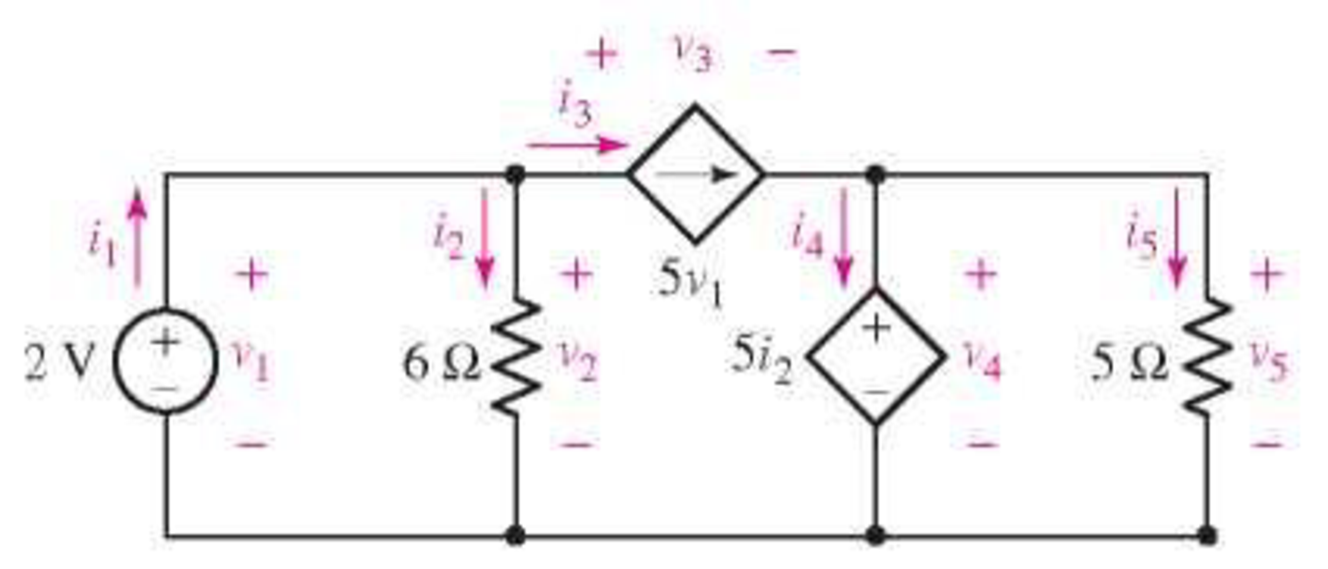
FIGURE 3.64
(a)
Find the value of current and voltage in the circuit.
Answer to Problem 23E
The current
The voltage
Explanation of Solution
Calculation:
The redrawn circuit is shown in Figure 1
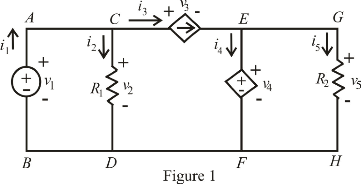
Refer to the Figure 1.
Since there is no voltage drop across branch
Here,
Refer to the Figure 1.
The expression for KCL at node
Here,
Refer to the Figure 1.
By ohm’s law the voltage across branch
Here,
Refer to the Figure 1
The expression for current
Refer to the Figure 1.
The expression for voltage
Here,
Refer to the Figure 1.
Since, the voltage across branch
Here,
By ohm’s law the voltage across branch is
The expression for KCL at node is
The expression for KVL across the loop
Refer to the Figure 1.
Substitute
Substitute
Rearrange for
Substitute 
Substitute
Substitute
Substitute
Substitute
Rearrange for
Substitute
Rearrange for
Substitute
Rearrange for
Conclusion:
Thus, the current
The voltage
(b)
Calculate the power absorbed by each element and verify total sum of power absorbed is zero.
Answer to Problem 23E
The power absorbed by independent voltage source is
The power absorbed by
The power absorbed by dependent current source is
The power absorbed by dependent voltage source is
The power absorbed by
Explanation of Solution
Formula used:
Refer to the Figure 1.
The expression for power supply by the voltage source from branch
Here,
The expression for power absorbed by resistance
The expression for power supply by the current dependent source from branch
The expression for power supply by the voltage dependent source from branch
The expression for power dissipate by the resistance
The expression for sum of total power absorbed in the circuit is,
Calculation:
Refer to the Figure 1.
Substitute
Substitute
Substitute
Substitute
Substitute
Substitute
Conclusion:
Thus, the power absorbed by independent voltage source is
The power absorbed by
The power absorbed by dependent current source is
The power absorbed by dependent voltage source is
The power absorbed by
Want to see more full solutions like this?
Chapter 3 Solutions
Engineering Circuit Analysis


- 4. Calculate the voltage across and the current through resistor R3. All values are given in scientific notation for Volts, Amps, and Ohms. (Hint: you may use source transformations if this assists in your analysis) + R1 m 1k V1 5 R2 m 3k R3 2k R4 6k I1 2m ↑arrow_forwardThe expected value of the voltage across a resistor is 240 V. However, measurement yields a value of 210 V. Calculate: a) Absolute error b) Percentage error c) Absolute accuracy d) Relative accuracy.arrow_forward6. A local restaurant has a neon sign constructed from 12 separate bulbs; when a bulb fails, it appears as an infinite resistance and cannot conduct current. In wiring the sign, the manufacturer offers two options (Fig. 3.48). From what you've learned about KCL, which one should the restaurant owner select? Еxplain. EXT\AT\RALPH'S, EAT AT RALPH'S IFIGURE 3.48 CS Scannec with CamScannerarrow_forward
- Determine the current labeled / in each of the circuits of Fig. 3.50. 7A ww ЗА 1.5 V. 2 A 9 A( (a) (b) (c) IFIGURE 3.50arrow_forwardIn Figure 3, the components are found to have the values: R1 = 50 ohms; R2 = 30 ohms; R3 = 45 ohms; Ea = 100 volts; Eb = 100 volts. (a) Using the procedures in Part B- Superposition Theorem, identify the values of all currents and show the details of your simulations. (b) What would be the results if one of the sources, say Eb, was reversed in the circuit? Verify your answer through simulation.arrow_forwardQ3// i) Find the total energy stored in the circuit of Figure 3. 2H 3 H 12 V 6 A 2F Figure 3arrow_forward
- Computed (Show complete solutions and redraw as you answer) Using the circuit shown in Fig. 3. 1 and the value of the DC power supply as the theoreticalvalue of the total voltage, compute and record, total current, voltages across each resistor, and currents flowing in each resistor using Voltage and Current Divider Theorem.arrow_forward3) C1=44μF, C2=19μF, C3=43μF, and a voltage Vab=34V is applied accross points a and b. After C1 is fully charged, the switch is thrown to the right. What is the final voltage on C2? Express your answer in units of V(Volts) using one decimal place.arrow_forwardA. Explain the relation between current and voltage in the basic component of electrical circuit. B. Find the equivalent resistance of the circuit given in figure 3 between A and B, between E and F E Fig 3 A www fur 252 452 1Q B 89 www D 202 www Farrow_forward
- Problem 3.7: Find ia and ig in the circuit i 15 N $ 120 125 V i, ,20 Ω 13 Ω 350arrow_forwardI need help solving 3.11arrow_forward7. If a third resistor (R3), identical to the other two, is added in parallel with the first two, then the electric potential difference (voltage drop) across each of the three individual resistors will a. increase. b. decrease c. remain the same 8. Which of the following statements is true about resistance? (State True or False AND EXPLAIN YOUR REASON AND SHOW CALCULATIONS).arrow_forward
 Introductory Circuit Analysis (13th Edition)Electrical EngineeringISBN:9780133923605Author:Robert L. BoylestadPublisher:PEARSON
 Delmar's Standard Textbook Of ElectricityElectrical EngineeringISBN:9781337900348Author:Stephen L. HermanPublisher:Cengage Learning
 Programmable Logic ControllersElectrical EngineeringISBN:9780073373843Author:Frank D. PetruzellaPublisher:McGraw-Hill Education
 Fundamentals of Electric CircuitsElectrical EngineeringISBN:9780078028229Author:Charles K Alexander, Matthew SadikuPublisher:McGraw-Hill Education
 Electric Circuits. (11th Edition)Electrical EngineeringISBN:9780134746968Author:James W. Nilsson, Susan RiedelPublisher:PEARSON
 Engineering ElectromagneticsElectrical EngineeringISBN:9780078028151Author:Hayt, William H. (william Hart), Jr, BUCK, John A.Publisher:Mcgraw-hill Education,