
Mechanics of Materials (10th Edition)
10th Edition
ISBN: 9780134319650
Author: Russell C. Hibbeler
Publisher: PEARSON
expand_more
expand_more
format_list_bulleted
Videos
Textbook Question
Chapter 3.4, Problem 3.7P
The rigid beam is supported by a pin at C and an A-36 steel guy wire AB. If the wire has a diameter of 0.2 in., determine how much it stretches when a distributed load of w = 100 lb/ft acts on the beam. The material remains elastic.
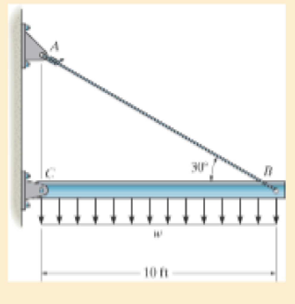
Probs. 3–7/8
Expert Solution & Answer
Want to see the full answer?
Check out a sample textbook solution
Students have asked these similar questions
The pole is supported by a pin at B and A-36 steel guy wire AC. If the wire has a diameter of
0.2. Modulus of Elasticity of Steel = 200GPA or 29x103 ksi Poisson's ratio of steel=0.321
a. Determine how much the wire stretches when the horizontal force acts on the pole.
3 ft
30
D 2.5 kip
4 ft
B
b. Determine the change in the wire's radius
c. At what angle is the principal stresses on pole BC? Use Mohr's Circle.
d. What is the principal stress in pol BC? Use Mohr's Circle
e. Draw the stresses on a unit element acting on 35-degree clockwise direction of pole BC. Use
Mohr's Circle.
f. What are the principal stresses in point D? Use Mohr's Circle. (answer in ksi)
g. At what angle is the principal stresses acting on point D? Use Mohr 's Circle.
h. Draw the stresses on a unit element acting on 35degree-clockwise direction of point D. Use Mohr's
Circle. (answer in ksi)
4.
The rigid lever arm is supported by two A-36 steel
wires having the same diameter of 4 mm. If a force of
P = 3 kN is applied to the handle, determine the force
developed in both wires and their corresponding elongations.
Consider A-36 steel as an elastic-perfectly plastic material.
450 mm
150 mm
150 mm
30
300 mm
B.
*3-8. The strut is supported by a pin at C and an A-36
steel guy wire AB. If the wire has 'a diameter of 5 mm,
determine how much it stretches when the distributed load
acts on the strut.
60
3.4 kN/m
2.7 m
Chapter 3 Solutions
Mechanics of Materials (10th Edition)
Ch. 3.4 - Define a homogeneous material.Ch. 3.4 - Indicate the points on the stress-strain diagram...Ch. 3.4 - Define the modulus of elasticity E.Ch. 3.4 - At room temperature, mild steel is a ductile...Ch. 3.4 - Engineering stress and strain are calculated using...Ch. 3.4 - As the temperature increases the modulus of...Ch. 3.4 - A 100-mm-long rod has a diameter of 15 mm. If an...Ch. 3.4 - A bar has a length of 8 in. and cross-sectional...Ch. 3.4 - A 10-mm-diameter rod has a modulus of elasticity...Ch. 3.4 - The material for the 50-mm-long specimen has the...
Ch. 3.4 - The material for the 50-mm-long specimen has the...Ch. 3.4 - If the elongation of wire BC is 0.2 mm after the...Ch. 3.4 - A tension test was performed on a steel specimen...Ch. 3.4 - Data taken from a stress-strain test for a ceramic...Ch. 3.4 - Data taken from a stress-strain test for a ceramic...Ch. 3.4 - The stress-strain diagram for a steel alloy having...Ch. 3.4 - The stress-strain diagram for a steel alloy having...Ch. 3.4 - The stress-strain diagram for a steel alloy having...Ch. 3.4 - The rigid beam is supported by a pin at C and an...Ch. 3.4 - The rigid beam is supported by a pin at C and an...Ch. 3.4 - Acetal plastic has a stress-strain diagram as...Ch. 3.4 - The stress-strain diagram for an aluminum alloy...Ch. 3.4 - The stress-strain diagram for an aluminum alloy...Ch. 3.4 - The stress-strain diagram for an aluminum alloy...Ch. 3.4 - A bar having a length of 5 in. and cross-sectional...Ch. 3.4 - The rigid pipe is supported by a pin at A and an...Ch. 3.4 - The rigid pipe is supported by a pin at A and an...Ch. 3.4 - Direct tension indicators are sometimes used...Ch. 3.4 - The rigid beam is supported by a pin at C and an...Ch. 3.4 - The rigid beam is supported by a pin at C and an...Ch. 3.4 - The stress-strain diagram for a bone is shown, and...Ch. 3.4 - The stress-strain diagram for a bone is shown and...Ch. 3.4 - The two bars are made of a material that has the...Ch. 3.4 - The two bars are made of a material that has the...Ch. 3.4 - The pole is supported by a pin at C and an A-36...Ch. 3.4 - The bar DA is rigid and is originally held in the...Ch. 3.7 - A 100-mm-long rod has a diameter of 15 mm. If an...Ch. 3.7 - A solid circular rod that is 600 mm long and 20 mm...Ch. 3.7 - A 20-mm-wide block is firmly bonded to rigid...Ch. 3.7 - A 20-mm-wide block is bonded to rigid plates at...Ch. 3.7 - The acrylic plastic rod is 200 mm long and 15 mm...Ch. 3.7 - The plug has a diameter of 30 mm and fits within a...Ch. 3.7 - The elastic portion of the stress-strain diagram...Ch. 3.7 - The elastic portion of the stress-strain diagram...Ch. 3.7 - The brake pads for a bicycle tire are made of...Ch. 3.7 - The lap joint is connected together using a 1.25...Ch. 3.7 - The lap joint is connected together using a 1.25...Ch. 3.7 - The rubber block is subjected to an elongation of...Ch. 3.7 - The shear stress-strain diagram for an alloy is...Ch. 3.7 - A shear spring is made from two blocks of rubber,...Ch. 3 - The elastic portion of the tension stress-strain...Ch. 3 - The elastic portion of the tension stress-strain...Ch. 3 - The rigid beam rests in the horizontal position on...Ch. 3 - The wires each have a diameter of 12 in., length...Ch. 3 - The wires each have a diameter of 12 in., length...Ch. 3 - diameter steel bolts. If the clamping force in...Ch. 3 - The stress-strain diagram for polyethylene, which...Ch. 3 - The pipe with two rigid caps attached to its ends...Ch. 3 - The 8-mm-diameter bolt is made of an aluminum...Ch. 3 - An acetal polymer block is fixed to the rigid...
Knowledge Booster


Learn more about
Need a deep-dive on the concept behind this application? Look no further. Learn more about this topic, mechanical-engineering and related others by exploring similar questions and additional content below.Similar questions
- A bar having a length of 125 mm and cross-sectional area of 437.5 mm2 is subjected to an axial force of 40 kN. If 3-13. the bar stretches 0.05 mm, determine the modulus of elasticity of the material. The material has linear-elastic behavior. 40 kN 40 kN -125 mm Prob. 3–13arrow_forwardThe strut is supported by a pin at C and an A-36 steel guy wire AB. If the wire has a diameter of 1,2 m , determine how much it stretches when the distributed load acts on the strut.arrow_forwardTHE ALUMINUM MACHINE PART IS SUBJECTED TO A MOMENT M = 75 NM. DETERMINE THE MAXIMUM TENSILE AND COMPRESSIVE BENDING FORCES IN THE PART. 20 mm 10 mm 20 mm 10 mm 10 mm 10 mm B 10 mm M = 75 N-m 40 mmarrow_forward
- 3–26. The thin-walled tube is subjected to an axial force of 40 kN. If the tube elongates 3 mm and its circumference decreases 0.09 mm, determine the modulus of elasticity, Poisson's ratio, and the shear modulus of the tube's material. The material behaves elastically. 40 kN 900 mm | 10 mm 40 kN 12.5 mmarrow_forwardThe bar is made of an aluminum alloy having a stress–strain diagram that can be approximated by the straight line segments shown. Assuming that this diagram is the same for both tension and compression, determine the moment the bar will support if the maximum strain at the top and bottom fibers of the beam is Pmax = 0.05.arrow_forward20 mm 20 mm 4. The simply supported beam on the right is built up from three boards by nailing them together as shown. If P = 12 kN, determine the maximum allowable spacing s of the nails to support the load, if each nail can resist a shear force of 1.5 kN. 1 m m B 100 mm 25 mm- 25 mm 200 mm 25 mmarrow_forward
- The rigid beam is supported by three 25-mm diameter A-36 steel rods. If the beam supports the force of P=230 kN, determine the force developed in each rod. Consider the steel to be an elastic perfectly plastic material. Detailed solutionarrow_forwardThe bent bar is supported by smooth journal bearings at A, B and C and is subjected to couple moment of 200 N.m. Determine the support reaction at each of the smooth journal bearings. 200 N.m /0.4 m/ B 0.7 m 0.6 m Figure 2arrow_forward1-7. The cable will fail when subjected to a tension of 800ON Determine the largest vertical load P the frame will support and calculate the internal normal force, shear force, and moment at the cross section through point C for this loading. B 0.1' m 0.5 m A -0.75 m- -0.75 m -0.75 m Parrow_forward
- The steel bar has the original dimensions shown in the figure. If it is subjected to an axial load of 50 kN, determine the change in its length and its new cross-sectional dimensions at section a–a. Est = 200 GPa, nst = 0.29.arrow_forwardDetermine the reaction forces R1 and R2 and show the shear and bending moment diagram. Data: Point load (left-most) = 90.126 N Uniformly distributed load (80mm to 260mm) = 0.14444 N/mm Uniformly distributed load (160mm to 180mm) = 6.5 N/mmarrow_forwardThe rigid lever arm is supported by two A-36 steel wires having the same diameter of 4 mm. If a force of P = 3 kN is applied to the handle, determine the force developed in both wires and their corresponding elongations. Consider A-36 steel as an elastic perfectly plastic material.arrow_forward
arrow_back_ios
SEE MORE QUESTIONS
arrow_forward_ios
Recommended textbooks for you
 Elements Of ElectromagneticsMechanical EngineeringISBN:9780190698614Author:Sadiku, Matthew N. O.Publisher:Oxford University Press
 Mechanics of Materials (10th Edition)Mechanical EngineeringISBN:9780134319650Author:Russell C. HibbelerPublisher:PEARSON
 Thermodynamics: An Engineering ApproachMechanical EngineeringISBN:9781259822674Author:Yunus A. Cengel Dr., Michael A. BolesPublisher:McGraw-Hill Education
 Control Systems EngineeringMechanical EngineeringISBN:9781118170519Author:Norman S. NisePublisher:WILEY
 Mechanics of Materials (MindTap Course List)Mechanical EngineeringISBN:9781337093347Author:Barry J. Goodno, James M. GerePublisher:Cengage Learning
 Engineering Mechanics: StaticsMechanical EngineeringISBN:9781118807330Author:James L. Meriam, L. G. Kraige, J. N. BoltonPublisher:WILEY
Elements Of Electromagnetics
Mechanical Engineering
ISBN:9780190698614
Author:Sadiku, Matthew N. O.
Publisher:Oxford University Press
Mechanics of Materials (10th Edition)
Mechanical Engineering
ISBN:9780134319650
Author:Russell C. Hibbeler
Publisher:PEARSON
Thermodynamics: An Engineering Approach
Mechanical Engineering
ISBN:9781259822674
Author:Yunus A. Cengel Dr., Michael A. Boles
Publisher:McGraw-Hill Education
Control Systems Engineering
Mechanical Engineering
ISBN:9781118170519
Author:Norman S. Nise
Publisher:WILEY
Mechanics of Materials (MindTap Course List)
Mechanical Engineering
ISBN:9781337093347
Author:Barry J. Goodno, James M. Gere
Publisher:Cengage Learning
Engineering Mechanics: Statics
Mechanical Engineering
ISBN:9781118807330
Author:James L. Meriam, L. G. Kraige, J. N. Bolton
Publisher:WILEY
Mechanics of Materials Lecture: Beam Design; Author: UWMC Engineering;https://www.youtube.com/watch?v=-wVs5pvQPm4;License: Standard Youtube License