
Basic Engineering Circuit Analysis
11th Edition
ISBN: 9781118539293
Author: J. David Irwin, R. Mark Nelms
Publisher: WILEY
expand_more
expand_more
format_list_bulleted
Concept explainers
Videos
Textbook Question
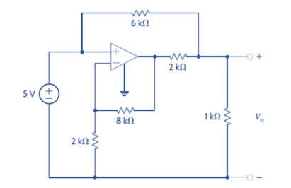
Chapter 4, Problem 4PFE.5TP
What is the voltage
a. 3 V c. 8 V
b. 6 V d. 5 V
Expert Solution & Answer
Want to see the full answer?
Check out a sample textbook solution
Students have asked these similar questions
Q4/ Reduce the system shown below by using Masson's method, then convert it to
Block diagram.
-H1
GI
H2
G2
G8
G7
H3
G3
G4
H7
-H9
H10
G5
H5
G6
-H6
Qn4...2
A:19
A docs.google.com
In the circuit in the Fig. below, reduce the
resistance R3 will lead to a reducing of,
choose all that possible options: *
R1
V
R2
R3
Power dissipated in R2
Voltage across R3.
None will be affected.
Voltage across R1
Current through R3.
When a group of resistors are connected in
parallel, the total resistance is *
Less than the smallest resistance.
Between the smallest and greatest
resistance.
Greater than the smallest resistance.
Sum of the resistances
Chapter 4 Solutions
Basic Engineering Circuit Analysis
Ch. 4 - An amplifier has a gain of 15 and the input...Ch. 4 - An amplifier has a gain of 5 and the output...Ch. 4 - An op-amp based amplifier has supply voltages of...Ch. 4 - For an ideal op-amp, the voltage gain and input...Ch. 4 - Revisit your answers in Problem 4.4 under the...Ch. 4 - Revisit the exact analysis of the inverting...Ch. 4 - Revisit the exact analysis of the inverting...Ch. 4 - An op-amp based amplifier has 18V supplies and a...Ch. 4 - Assuming an ideal op-amp, determine the voltage...Ch. 4 - Assuming an ideal op-amp, determine the voltage...
Ch. 4 - Assuming an ideal op-amp in Fig. P4.11, determine...Ch. 4 - Assuming an ideal op-amp, find the voltage gain of...Ch. 4 - Assuming an ideal op-amp in Fig. P4.13, determine...Ch. 4 - Determine the gain of the amplifier in Fig. P4.14....Ch. 4 - For the amplifier in Fig. P4.15, find the gain and...Ch. 4 - Using the ideal op-amp assumptions, determine the...Ch. 4 - Using the ideal op-amp assumptions, determine...Ch. 4 - In a useful application, the amplifier drives a...Ch. 4 - The op-amp in the amplifier in Fig. P4.19 operates...Ch. 4 - For the amplifier in Fig. P4.20, the maximum value...Ch. 4 - For the circuit in Fig. P4.21, (a) find Vo in...Ch. 4 - Find Vo in the circuit in Fig. P4.22, assuming...Ch. 4 - The network in Fig. P4.23 is a current-to-voltage...Ch. 4 - Prob. 24PCh. 4 - Determine the relationship between v1 and io in...Ch. 4 - Find Vo in the network in Fig. P4.26 and explain...Ch. 4 - Determine the expression for vo in the network in...Ch. 4 - Show that the output of the circuit in Fig. P4.28...Ch. 4 - Find vo in the network in Fig. P4.29.Ch. 4 - Find the voltage gain of the op-amp circuit shown...Ch. 4 - Determine the relationship between and in the...Ch. 4 - Prob. 32PCh. 4 - For the circuit in Fig. P4.33, find the value of...Ch. 4 - Find Vo in the circuit in Fig. P4.34.Ch. 4 - Find Vo in the circuit in Fig. P4.35.Ch. 4 - Determine the expression for the output voltage,...Ch. 4 - Determine the output voltage, of the noninverting...Ch. 4 - Find the input/output relationship for the current...Ch. 4 - Find V0 in the circuit in Fig. P4.39.Ch. 4 - Find Vo in the circuit in Fig. P4.40.Ch. 4 - Find the expression for in the differential...Ch. 4 - Find vo in the circuit in Fig. P4.42.Ch. 4 - Find the output voltage, vo, in the circuit in...Ch. 4 - The electronic ammeter in Example 4.7 has been...Ch. 4 - Given the summing amplifier shown in Fig. 4PFE-l,...Ch. 4 - Determine the output voltage V0 of the summing...Ch. 4 - What is the output voltage V0 in Fig. 4PFE-3. a....Ch. 4 - What value of Rf in the op-amp circuit of Fig....Ch. 4 - What is the voltage Vo in the circuit in Fig....
Knowledge Booster


Learn more about
Need a deep-dive on the concept behind this application? Look no further. Learn more about this topic, electrical-engineering and related others by exploring similar questions and additional content below.Similar questions
- a)Write the relationship between V1 , R1 , Rc and Ic .b) Write the relationship between V2 , R2 , Rc and Ic .c) Write the relationship between V3 , R3 , Rc and Ic .d) Determine the values of Rc and Ic .e) Determine the value of R3 .arrow_forwardhow did they get the formula for Gv the gain from the diagram?arrow_forwardcal Engineering Find the equivalent resistance at terminals a-b for each of the networks in the following Lecture 4- Resistors Analysis 2015-2016 rk circuits. R. R. R R R. bo (a) (b) (c) R. 3R RS 2R 3R (d) (e) ww ww wwarrow_forward
- It is desired to measure the voltage of the R2 load in the circuit given on the side. Find the relative error of the measurement.arrow_forwardConsider the circuit below. R4 E R3- R1 R2 b. a Rs Ro 10Varrow_forwardplease only solve problem 4-4 but use 4-3 as reference to solve 4-4 as explained. Thank youarrow_forward
- P.2-8-For the following cet. Fiad_ the ove-ell Ry C Z2 L3 E Q E. R3 Liarrow_forwardPROBLEM [ B4]: Two resistors R, and R, are connected in parallel in an electric circuit. If the resistance R, is changed from 16 to 16.2 ohms and R, is changed from 28 to 27.8 ohms, find the absolute change, relative change and percentage change in the total resistance R.arrow_forwardIf two resistances of 10 Q and 5 Q are connected in parallel. Find equivalent resistance. O a. 33.33 m 2 b. 3333.33 m O C. 333.33 m 2 O d. 3.33 K Oarrow_forward
arrow_back_ios
SEE MORE QUESTIONS
arrow_forward_ios
Recommended textbooks for you
 Introductory Circuit Analysis (13th Edition)Electrical EngineeringISBN:9780133923605Author:Robert L. BoylestadPublisher:PEARSON
 Delmar's Standard Textbook Of ElectricityElectrical EngineeringISBN:9781337900348Author:Stephen L. HermanPublisher:Cengage Learning
 Programmable Logic ControllersElectrical EngineeringISBN:9780073373843Author:Frank D. PetruzellaPublisher:McGraw-Hill Education
 Fundamentals of Electric CircuitsElectrical EngineeringISBN:9780078028229Author:Charles K Alexander, Matthew SadikuPublisher:McGraw-Hill Education
 Electric Circuits. (11th Edition)Electrical EngineeringISBN:9780134746968Author:James W. Nilsson, Susan RiedelPublisher:PEARSON
 Engineering ElectromagneticsElectrical EngineeringISBN:9780078028151Author:Hayt, William H. (william Hart), Jr, BUCK, John A.Publisher:Mcgraw-hill Education,
Introductory Circuit Analysis (13th Edition)
Electrical Engineering
ISBN:9780133923605
Author:Robert L. Boylestad
Publisher:PEARSON
Delmar's Standard Textbook Of Electricity
Electrical Engineering
ISBN:9781337900348
Author:Stephen L. Herman
Publisher:Cengage Learning
Programmable Logic Controllers
Electrical Engineering
ISBN:9780073373843
Author:Frank D. Petruzella
Publisher:McGraw-Hill Education
Fundamentals of Electric Circuits
Electrical Engineering
ISBN:9780078028229
Author:Charles K Alexander, Matthew Sadiku
Publisher:McGraw-Hill Education
Electric Circuits. (11th Edition)
Electrical Engineering
ISBN:9780134746968
Author:James W. Nilsson, Susan Riedel
Publisher:PEARSON
Engineering Electromagnetics
Electrical Engineering
ISBN:9780078028151
Author:Hayt, William H. (william Hart), Jr, BUCK, John A.
Publisher:Mcgraw-hill Education,
Thevenin's Theorem; Author: Neso Academy;https://www.youtube.com/watch?v=veAFVTIpKyM;License: Standard YouTube License, CC-BY