
Concept explainers
Videos
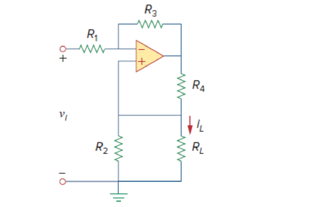
A voltage-to-current converter is shown in Fig. 5.110, which means that iL= Avi if R1R2 = R3R4. Find the constant term A.
Calculate the constant term A in the voltage-to-current converter in Figure 5.110.
Answer to Problem 93CP
The constant term A is
Explanation of Solution
Given data:
Refer Figure 5.110 in the textbook for the voltage-to-current converter circuit.
Calculation:
Modify the Figure 5.110 by indicating the node voltages. The modified circuit as shown in Figure 1.
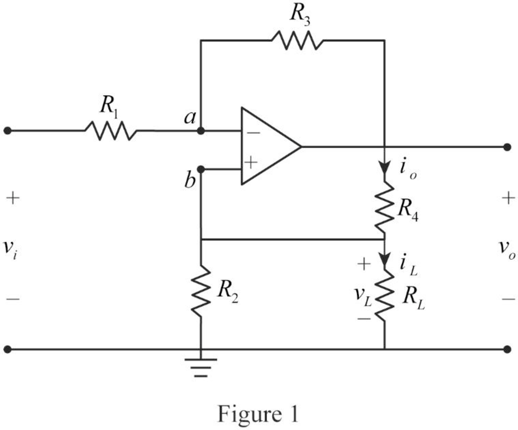
In Figure 1, the
Write the node voltage expression at node
From the general property of ideal op amp, consider that the voltage across the two input terminals of op amp is equal to zero.
Re-arrange the equation.
Consider the expression by using Figure 1.
Substitute
Substitute
Write the expression for the current
Write the expression for the current
Substitute Equation (4) in (5).
Consider the expression for the voltage
Substitute Equations (6) and (7) in (3).
Consider the given expression.
Re-arrange the Equation.
Compare Equations (8) and (9).
Re-arrange the Equation.
Conclusion:
Thus, the constant term A is
Want to see more full solutions like this?
Chapter 5 Solutions
Fundamentals of Electric Circuits


- Let us try example 5.6, page 250 Nise. Convert the following to signal flow graph. V₁(3) V₂(s) + G₁(s) V(s) 88 V₂(s)+Vs(s) G₂(s)arrow_forwardThe amplification factor and transconductance in a triode are 60 and 30 millimhos respectively. With constant grid voltage, find the change in the anode current (in mA) when the anode voltage is changed from 5 V to 20 V.arrow_forward1)What is the resolution of a D/A converter? A)It is the comparison between the actual output of the converter and its expected output. B)The ability to resolve between forward and reverse steps when sequenced over its entire range of inputs. C)It is the deviation between the ideal straight-line output and the actual output of the converter. D)It is the reciprocal of the number of discrete steps in the D/A output.arrow_forward
- A ZCS buck converter has the following parameters: L, = 5uH and Cr = 0.2uF. Fig. Q3(b) below depicts Ver (t). Find t, and t2. vcrt 1.4V5 t1 t2 Fig. Q3(b)arrow_forwardLMH_chapter3-part 1-homework [Protected View] PowerPoint ĐĂNG PHẠM HỒNG File Home Insert Design Transitions Animations Slide Show Review View Help Tell me what you want to do & Share 1 Chapter III HW15 AC Circuit Analysis Homework part 1 Reading: Chapter 05 Textbook: Fundamental of Electric Circuits Textbook 5.10 Find the gain v,/v, of the circuit in Fig. 5.49. 2 HW14 5.7 The op amp in Fig 5.46 has R, - 100 k, R, - 100 2, 4- 100,000. Find dhe dillerential volage e, and the output voltage v. 37 k2 10 k 100 A 20 kΩ I mv :) 3. HW15 5.10 Find the gain r/v, of the circait in Fig. 5.49. 10 k2 37 ko 20 k2 4 HW16 5.13 Find u, andi, in the circuit of Fig. 5.52. 3 1v O 100 k2 E90 ka 10 k2 50 kaarrow_forwardQ-2: Explain the saturation of a transistor. Find the given unknowns for the figure below. a. Rc. b. Rg c. Rp. d. VCE e. V Also find the voltage V, at cutoff. 12 V 2 mA Rc 7.6 V V B-80 024 V Q-3: Define Lso and lao, How are they related? Find the following f le corresponding to V = +750mv and Va = +5Varrow_forward
- Please illustrate simply in detail, what Superposition is in Analog and Digital Electronics,and please give as many examples as possible.arrow_forwardHW23 5.48 The circuit in Fig. 5.80 is a differential amplifier driven by a brige. Find v. 20 k2 80 k2 10 k2 30 k2 + 5 mV o- 40 k2 60 k2 20 k2 80 k2arrow_forwardV1 R1 V2 Da Db R2 www V3 Given that R1=2k, R2=1k, and Da and Db are Si Diodes: a. What is V3 in terms of V1 when Da is ON? b. What is V3 in terms of V1 when Db is ON? c. What is V3 in terms of V1 when Da and Db is OFF?arrow_forward
- 5.71 Determine v, in the op amp circuit of Fig. 5.97. 20 k2 100 k2 5 k2 ww 40 k2 ww ww 80 k2 2 V 10 kΩ 20 k2 10 k2 ww 3 V 50 k2 30 k2 wwarrow_forwardFind the value of R and the current through it in the following network shown below, where the current in branch OA (52) is zero. 1.5Q 20 10 V [Ans: Carrow_forwardYou have been asked to design a self bias circuit as shown in the figure below using a 9 V power supply. The transistor has VBg = 0.6 Vv, and ß = 100. The circuit should have Ic = 3 mA, VCE = Rclc and the voltage across resistor RĘ is half of Vce. Calculate the values of all resistors in the circuit to achieve the required bias. Hint: Consider the current in resistors R, and R1 much large than Ig (at least 10 times) to be able to ignore the base current compared to the current in these resistors. +Vc Ie Re Answer: R1 = 11 kn, R2 = 4 kN, Rc = 1.2 kn, Rg = 600 N. VCE REarrow_forward
 Introductory Circuit Analysis (13th Edition)Electrical EngineeringISBN:9780133923605Author:Robert L. BoylestadPublisher:PEARSON
 Delmar's Standard Textbook Of ElectricityElectrical EngineeringISBN:9781337900348Author:Stephen L. HermanPublisher:Cengage Learning
 Programmable Logic ControllersElectrical EngineeringISBN:9780073373843Author:Frank D. PetruzellaPublisher:McGraw-Hill Education
 Fundamentals of Electric CircuitsElectrical EngineeringISBN:9780078028229Author:Charles K Alexander, Matthew SadikuPublisher:McGraw-Hill Education
 Electric Circuits. (11th Edition)Electrical EngineeringISBN:9780134746968Author:James W. Nilsson, Susan RiedelPublisher:PEARSON
 Engineering ElectromagneticsElectrical EngineeringISBN:9780078028151Author:Hayt, William H. (william Hart), Jr, BUCK, John A.Publisher:Mcgraw-hill Education,