
Mechanics of Materials, 7th Edition
7th Edition
ISBN: 9780073398235
Author: Ferdinand P. Beer, E. Russell Johnston Jr., John T. DeWolf, David F. Mazurek
Publisher: McGraw-Hill Education
expand_more
expand_more
format_list_bulleted
Concept explainers
Videos
Textbook Question
Chapter 5.4, Problem 116P
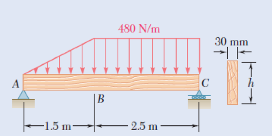
5.116 and 5.117 A timber beam is being designed to be supported and loaded as shown. (a) Using singularity functions, find the magnitude and location of the maximum bending moment in the beam. (b) Knowing that the available stock consists of beams with an allowable normal stress of 12 MPa and a rectangular cross section of 30-mm width and depth h varying from 80 mm to 160 mm in 10-mm increments, determine the most economical cross section that can be used.
Fig. P5.116
Expert Solution & Answer
Want to see the full answer?
Check out a sample textbook solution
Students have asked these similar questions
A 6-x 10-in. timber beam has been strengthened by bolting two - x 2-in. steel straps
to it as shown below. The moduli of elasticity are 1.5 x 10⁶ psi for the wood and
30 x 106 psi for the steel. Knowing that the beam is bent about a horizontal axis by a
bending moment of 200 kip in, determine
(a) The maximum flexural stress in the wood.
(b) The maximum flexural stress in the steel.
10 in.
T
6 in..
wood
2 x 3/8 in. steel
4. A (250 mm) depth and (150mm) width rectangular beam is
subjected to maximum bending moment of (750 KN.m), Determine:
a. The maximum stress in the beam ?
b. If the value of Young Modulus (E) for the beam material is (200
GPa), find the radius of curvature for that portion of the beam where
the bending is maximum ?
c. The value of the longitudinal stress at a distance of (65mm) from
the top surface of the beam ?
Homework
A timber beam AB of length L and rectangular cross section carries
a single concentrated load P at its midpoint C. (a) Show that the ratio
Tm/Tm of the maximum values of the shearing and normal stresses in
the beam is equal to h/2L, where h and L are, respectively, the depth
and the length of the beam. (b) Determine the depth h and the width
b of the beam, knowing that L = 2 m, P = 40 KN, T, = 960 kPa,
and om = 12 MPa.
m
· L/2
C
- L/2·
A
В
Chapter 5 Solutions
Mechanics of Materials, 7th Edition
Ch. 5.1 - 5.1 through 5.6 For the beam and loading shown,...Ch. 5.1 - 5.1 through 5.6 For the beam and loading shown,...Ch. 5.1 - 5.1 through 5.6 For the beam and loading shown,...Ch. 5.1 - 5.1 through 5.6 For the beam and loading shown,...Ch. 5.1 - 5.1 through 5.6 For the beam and loading shown,...Ch. 5.1 - 5.1 through 5.6 For the beam and loading shown,...Ch. 5.1 - 5.7 and 5.8 Draw the shear and bending-moment...Ch. 5.1 - 5.7 and 5.8 Draw the shear and bending-moment...Ch. 5.1 - 5.9 and 5.10 Draw the shear and bending-moment...Ch. 5.1 - 5.9 and 5.10 Draw the shear and bending-moment...
Ch. 5.1 - 5.11 and 5.12 Draw the shear and bending-moment...Ch. 5.1 - 5.11 and 5.12 Draw the shear and bending-moment...Ch. 5.1 - 5.13 and 5.14 Assuming that the reaction of the...Ch. 5.1 - 5.13 and 5.14 Assuming that the reaction of the...Ch. 5.1 - 5.15 and 5.16 For the beam and loading shown,...Ch. 5.1 - 5.15 and 5.16 For the beam and loading shown,...Ch. 5.1 - For the beam and loading shown, determine the...Ch. 5.1 - For the beam and loading shown, determine the...Ch. 5.1 - 5.19 and 5.20 For the beam and loading shown,...Ch. 5.1 - 5.19 and 5.20 For the beam and loading shown,...Ch. 5.1 - Draw the shear and bending-moment diagrams for the...Ch. 5.1 - 5.22 and 5.23 Draw the shear and bending-moment...Ch. 5.1 - 5.22 and 5.23 Draw the shear and bending-moment...Ch. 5.1 - 5.24 and 5.25 Draw the shear and bending-moment...Ch. 5.1 - 5.24 and 5.25 Draw the shear and bending-moment...Ch. 5.1 - Knowing that W = 12 kN, draw the shear and...Ch. 5.1 - Determine (a) the magnitude of the counterweight W...Ch. 5.1 - Determine (a) the distance a for which the...Ch. 5.1 - Knowing that P = Q = 480 N, determine (a) the...Ch. 5.1 - Solve Prob. 5.29, assuming that P = 480 N and Q =...Ch. 5.1 - Determine (a) the distance a for which the...Ch. 5.1 - A solid steel rod of diameter d is supported as...Ch. 5.1 - A solid steel bar has a square cross section of...Ch. 5.2 - Using the method of Sec. 5.2, solve Prob. 5.1a....Ch. 5.2 - Using the method of Sec. 5.2, solve Prob. 5.2a....Ch. 5.2 - Prob. 36PCh. 5.2 - Prob. 37PCh. 5.2 - Using the method of Sec. 5.2, solve Prob. 5.5a....Ch. 5.2 - Using the method of Sec. 5.2, solve Prob. 5.6a....Ch. 5.2 - Using the method of Sec. 5.2, solve Prob. 5.7. 5.7...Ch. 5.2 - Using the method of Sec. 5.2, solve Prob. 5.8. 5.7...Ch. 5.2 - Prob. 42PCh. 5.2 - Using the method of Sec. 5.2, solve Prob. 5.10....Ch. 5.2 - 5.44 and 5.45 Draw the shear and bending-moment...Ch. 5.2 - 5.44 and 5.45 Draw the shear and bending-moment...Ch. 5.2 - Prob. 46PCh. 5.2 - Prob. 47PCh. 5.2 - Prob. 48PCh. 5.2 - Using the method of Sec. 5.2, solve Prob. 5.20....Ch. 5.2 - 5.50 and 5.51 Determine (a) the equations of the...Ch. 5.2 - 5.50 and 5.51 Determine (a) the equations of the...Ch. 5.2 - 5.52 and 5.53 Determine (a) the equations of the...Ch. 5.2 - 5.52 and 5.53 Determine (a) the equations of the...Ch. 5.2 - 5.54 and 5.55 Draw the shear and bending-moment...Ch. 5.2 - 5.54 and 5.55 Draw the shear and bending-moment...Ch. 5.2 - 5.56 and 5.57 Draw the shear and bending-moment...Ch. 5.2 - 5.56 and 5.57 Draw the shear and bending-moment...Ch. 5.2 - 5.58 and 5.59 Draw the shear and bending-moment...Ch. 5.2 - 5.58 and 5.59 Draw the shear and bending-moment...Ch. 5.2 - Knowing that beam AB is in equilibrium under the...Ch. 5.2 - Knowing that beam AB is in equilibrium under the...Ch. 5.2 - The beam AB supports two concentrated loads P and...Ch. 5.2 - The beam AB supports a uniformly distributed load...Ch. 5.2 - Beam AB supports a uniformly distributed load of 2...Ch. 5.3 - 5.65 and 5.66 For the beam and loading shown,...Ch. 5.3 - 5.65 and 5.66 For the beam and loading shown,...Ch. 5.3 - 5.67 and 5.68 For the beam and loading shown,...Ch. 5.3 - 5.67 and 5.68 For the beam and loading shown,...Ch. 5.3 - 5.69 and 5.70 For the beam and loading shown,...Ch. 5.3 - 5.69 and 5.70 For the beam and loading shown,...Ch. 5.3 - 5.71 and 5.72 Knowing that the allowable normal...Ch. 5.3 - 5.71 and 5.72 Knowing that the allowable normal...Ch. 5.3 - 5.73 and 5.74 Knowing that the allowable normal...Ch. 5.3 - 5.73 and 5.74 Knowing that the allowable normal...Ch. 5.3 - 5.75 and 5.76 Knowing that the allowable normal...Ch. 5.3 - 5.75 and 5.76 Knowing that the allowable normal...Ch. 5.3 - 5.77 and 5.78 Knowing that the allowable normal...Ch. 5.3 - 5.77 and 5.78 Knowing that the allowable normal...Ch. 5.3 - A steel pipe of 100-mm diameter is to support the...Ch. 5.3 - Two metric rolled-steel channels are to be welded...Ch. 5.3 - Two rolled-steel channels are to be welded back to...Ch. 5.3 - Two L4 3 rolled-steel angles are bolted together...Ch. 5.3 - Assuming the upward reaction of the ground to be...Ch. 5.3 - Assuming the upward reaction of the ground to be...Ch. 5.3 - Determine the largest permissible distributed load...Ch. 5.3 - Solve Prob. 5.85, assuming that the cross section...Ch. 5.3 - Determine the largest permissible value of P for...Ch. 5.3 - Solve Prob. 5.87, assuming that the T-shaped beam...Ch. 5.3 - Beams AB, BC, and CD have the cross section shown...Ch. 5.3 - Beams AB, BC, and CD have the cross section shown...Ch. 5.3 - Each of the three rolled-steel beams shown...Ch. 5.3 - A 54-kip load is to be supported at the center of...Ch. 5.3 - A uniformly distributed load of 66 kN/m is to be...Ch. 5.3 - A roof structure consists of plywood and roofing...Ch. 5.3 - Solve Prob. 5.94, assuming that the 6-kN...Ch. 5.3 - Prob. 96PCh. 5.3 - Assuming that the front and rear axle loads remain...Ch. 5.4 - 5.98 through 5.100 (a) Using singularity...Ch. 5.4 - 5.98 through 5.100 (a) Using singularity...Ch. 5.4 - 5.98 through 5.100 (a) Using singularity...Ch. 5.4 - 5.101 through 5.103 (a) Using singularity...Ch. 5.4 - Prob. 102PCh. 5.4 - Prob. 103PCh. 5.4 - Prob. 104PCh. 5.4 - Prob. 105PCh. 5.4 - Prob. 106PCh. 5.4 - Prob. 107PCh. 5.4 - Prob. 108PCh. 5.4 - Prob. 109PCh. 5.4 - Prob. 110PCh. 5.4 - Prob. 111PCh. 5.4 - Prob. 112PCh. 5.4 - 5.112 and 5.113 (a) Using singularity functions,...Ch. 5.4 - Prob. 114PCh. 5.4 - 5.114 and 5.115 A beam is being designed to be...Ch. 5.4 - 5.116 and 5.117 A timber beam is being designed to...Ch. 5.4 - Prob. 117PCh. 5.4 - Prob. 118PCh. 5.4 - Prob. 119PCh. 5.4 - 5.118 through 5.121 Using a computer and step...Ch. 5.4 - Prob. 121PCh. 5.4 - 5.122 and 5.123 For the beam and loading shown and...Ch. 5.4 - 5.122 and 5.123 For the beam and loading shown and...Ch. 5.4 - 5.124 and 5.125 For the beam and loading shown and...Ch. 5.4 - Prob. 125PCh. 5.5 - 5.126 and 5.127 The beam AB, consisting of a...Ch. 5.5 - Prob. 127PCh. 5.5 - 5.128 and 5.129 The beam AB, consisting of a...Ch. 5.5 - 5.128 and 5.129 The beam AB, consisting of a...Ch. 5.5 - Prob. 130PCh. 5.5 - Prob. 131PCh. 5.5 - Prob. 132PCh. 5.5 - 5.132 and 5.133 A preliminary design on the use of...Ch. 5.5 - Prob. 134PCh. 5.5 - Prob. 135PCh. 5.5 - Prob. 136PCh. 5.5 - Prob. 137PCh. 5.5 - Prob. 138PCh. 5.5 - Prob. 139PCh. 5.5 - Assuming that the length and width of the cover...Ch. 5.5 - Two cover plates, each 12 in. thick, are welded to...Ch. 5.5 - Two cover plates, each 12 in. thick, are welded to...Ch. 5.5 - Prob. 143PCh. 5.5 - Prob. 144PCh. 5.5 - Two cover plates, each 7.5 mm thick, are welded to...Ch. 5.5 - Prob. 146PCh. 5.5 - Prob. 147PCh. 5.5 - For the tapered beam shown, determine (a) the...Ch. 5.5 - Prob. 149PCh. 5.5 - Prob. 150PCh. 5.5 - Prob. 151PCh. 5 - Draw the shear and bending-moment diagrams for the...Ch. 5 - Draw the shear and bending-moment diagrams for the...Ch. 5 - Determine (a) the distance a for which the...Ch. 5 - For the beam and loading shown, determine the...Ch. 5 - Draw the shear and bending-moment diagrams for the...Ch. 5 - Beam AB, of length L and square cross section of...Ch. 5 - Prob. 158RPCh. 5 - Knowing that the allowable normal stress for the...Ch. 5 - Prob. 160RPCh. 5 - (a) Using singularity functions, find the...Ch. 5 - Prob. 162RPCh. 5 - Prob. 163RP
Knowledge Booster


Learn more about
Need a deep-dive on the concept behind this application? Look no further. Learn more about this topic, mechanical-engineering and related others by exploring similar questions and additional content below.Similar questions
- Determine the bending stress in a 1-meter simple beam with a concentrated load of 1.25 kN at midspan. The beam has a rectangular section with b = 2 in and h = 4 in. а. 1.78 с. 3.58 b. 2.56 d. Answer is not among the choicesarrow_forwardA beam carries the loading shown in Fig. 4. Determine, (a) the smallest allowable width b of the beam if the maximum allowable bending stress is 93.75 MN/m². (b) to reduce the weight, a bore was made at the center of the rectangle with a diameter of 60 mm, what is the second moment of area of the resulting shape? 3 m 2 kN/m B www. 9 m Fig. 4 8 kN 3 m D 0000 1 160 mmarrow_forward2. Determine the bending stress in a 1-meter simple beam with a concentrated load of 1.25 kN at midspan. The beam has a rectangular section with b = 2 in and h = 4 in. a. 1.78 с. 3.58 b. 2.56 d. Answer is not among the choicesarrow_forward
- (14) A beam of I-section is 2 in. wide and 4 in. deep with all sections 1/2 in. thick. It is supported at points 5ft. apart, and carries a concentrated load of 400 lb at a distance of 2ft from the left support. (a) Determine the horizontal shear in the vertical section just to the left of the load and at distances of 0, 1, and 2 in. from the neutral axis. (b) Determine the horizontal shear in the vertical section just to the right of the left support and at distances 0, 1, and 1 ½ in. from the neutral axis.arrow_forward5.16 The box beam is made by nailing four 2-in. by 8-in. planks together as shown. (a) Show that the moment of inertia of the cross-sectional area about the neutral axis is 981.3 in.. (b) Given that wo 300 lb/ft, find the largest allowable force P if the bending stress is limited to 1400 psi. 8 in.2 in. 8 in. 9 f 3 ft 2 in. FIG. P5.16arrow_forward0.6 m 25 kN/m 40 kN 1.8 m 40 KN C 0.6 m D PROBLEM 5.108 (a) Using singularity functions, write the equations for the shear and bending moment for the beam and loading shown. (b) Determine the maximum value of the bending moment in the beam.arrow_forward
- For the beam shown, calculate the magnitude of the bending stress (in psi) at the top of the beam on a section 1.84 feet to the right of B if P = 1317 lb, Q = 4548 lb, w = 1.5 in, L = 8.66 in, b = 4.03 in, and h = 1.67 in. Round off the final answer to two decimal places. ... P Q W D 2 ft 3 ft——3 ft— 2 ft Add your answerarrow_forwardKnowing that the bending moment in the reinforced concrete beam is 1100 kip?ft and that the modulus of elasticity is 3.625 *106 psi for the concrete and 29* 106 psi for the steel, determine (a) the stress in the steel, (b) the maximum stress in the concretearrow_forward(13) A beam is to be rectangular in section with depth twice the width. The distance between supports is 6 feet and there are two concentrated downward loads : 6,000 lb 18 in. from the left support, and 5,000 lb., 40 in. from the left support. (a) Draw shear and bending-moment diagrams. (b) Using steel with E equal to 30,000,000 psi and ultimate strength of 75,000 psi, determine the beam dimensions if the maximum stress is to be 15,000 psi. (c) Using cast iron with E equal to 10,000,000 psi and ultimate strength of 30,000 psi, determine the beam dimensions if the maximum stress is 5,000 psi.arrow_forward
- A 3.6 m long overhang timber beam AC with a 2.4 m span AB is to be designed to support the distributed and concentrated loads shown. a. Determine the maximum moment of the beam. b. Determine the minimum required depth of the beam if the allowable stress is 12 MPa. c. Determine the maximum shearing stress of the required beam. 20 kN 90 mm 60 kN/m 2.4 m 1.2 marrow_forwardFive metal strips, each of 0.5 * 1.5-in. cross section, are bonded together to form the composite beam shown. The modulus of elasticity is 30* 106 psi for the steel, 15 *106 psi for the brass, 10 *106 psi for the aluminum. Knowing that the beam is bent about a horizontal axis by a couple of moment 12 kip·in., determine (a) the maximum stress in each of the three metals, (b) the radius of curvature of the composite beam.arrow_forwardDetermine the largest permissible value of P for the beam and loading shown, knowing that the allowable normal stress is +4 ksi in tension and -9 ksi in compression. Solve for P (Note: Draw the shear and moment diagram). |P |P 1 in. -10 in. 10 in- A E 5 in. B |C D 1 in. 7 in. 60 in. 60 in.arrow_forward
arrow_back_ios
SEE MORE QUESTIONS
arrow_forward_ios
Recommended textbooks for you
 Elements Of ElectromagneticsMechanical EngineeringISBN:9780190698614Author:Sadiku, Matthew N. O.Publisher:Oxford University Press
 Mechanics of Materials (10th Edition)Mechanical EngineeringISBN:9780134319650Author:Russell C. HibbelerPublisher:PEARSON
 Thermodynamics: An Engineering ApproachMechanical EngineeringISBN:9781259822674Author:Yunus A. Cengel Dr., Michael A. BolesPublisher:McGraw-Hill Education
 Control Systems EngineeringMechanical EngineeringISBN:9781118170519Author:Norman S. NisePublisher:WILEY
 Mechanics of Materials (MindTap Course List)Mechanical EngineeringISBN:9781337093347Author:Barry J. Goodno, James M. GerePublisher:Cengage Learning
 Engineering Mechanics: StaticsMechanical EngineeringISBN:9781118807330Author:James L. Meriam, L. G. Kraige, J. N. BoltonPublisher:WILEY
Elements Of Electromagnetics
Mechanical Engineering
ISBN:9780190698614
Author:Sadiku, Matthew N. O.
Publisher:Oxford University Press
Mechanics of Materials (10th Edition)
Mechanical Engineering
ISBN:9780134319650
Author:Russell C. Hibbeler
Publisher:PEARSON
Thermodynamics: An Engineering Approach
Mechanical Engineering
ISBN:9781259822674
Author:Yunus A. Cengel Dr., Michael A. Boles
Publisher:McGraw-Hill Education
Control Systems Engineering
Mechanical Engineering
ISBN:9781118170519
Author:Norman S. Nise
Publisher:WILEY
Mechanics of Materials (MindTap Course List)
Mechanical Engineering
ISBN:9781337093347
Author:Barry J. Goodno, James M. Gere
Publisher:Cengage Learning
Engineering Mechanics: Statics
Mechanical Engineering
ISBN:9781118807330
Author:James L. Meriam, L. G. Kraige, J. N. Bolton
Publisher:WILEY
Everything About COMBINED LOADING in 10 Minutes! Mechanics of Materials; Author: Less Boring Lectures;https://www.youtube.com/watch?v=N-PlI900hSg;License: Standard youtube license