
Videos
(a)
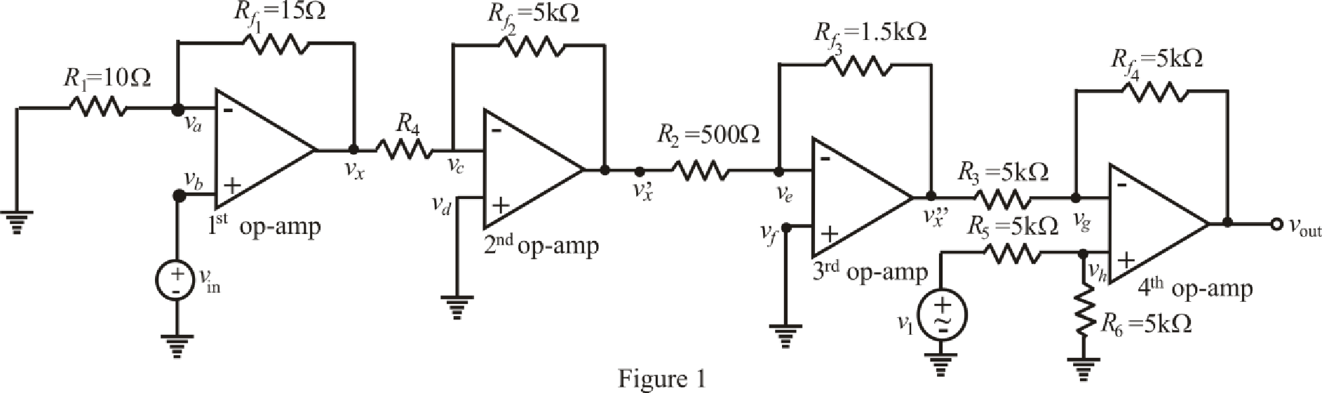
Find the output voltage of the circuit.
(a)
Answer to Problem 24E
The output voltage of combined circuit is
Explanation of Solution
Given data:
Combine the two circuits by eliminating the
Connect the output of circuit shown in FIGURE 6.49 to left-hand terminal of
Value of resistance
Value of input voltage of 1st op amp
Value of input voltage of 4th op amp
Calculation:
The redrawn circuit from given data is shown in Figure 1 as follows.
The expression for nodal analysis at node voltage
Here,
The expression for the virtual ground concept across 1st op amp is as follows.
Substitute
Rearrange for
Rearrange for
Substitute
Substitute
The expression for the nodal analysis at node voltage
Here,
The expression for the virtual ground concept across 2nd op amp is as follows,
Substitute
Rearrange for
Substitute
The expression for the nodal analysis at node voltage
Here,
The expression for the virtual ground concept across 3rd op amp is as follows.
Substitute
Rearrange for
Substitute
The expression for the nodal analysis at node voltage
Here,
The expression for the nodal analysis at node voltage
Here,
The expression for the virtual ground concept across 3rd op amp is as follows,
Simplify equation (14) for
Rearrange for
Substitute
Rearrange for
Rearrange for
Substitute
Solve for
Conclusion:
Thus, the output voltage of combined circuit is
(b)
Find the output voltage of the circuit.
(b)
Answer to Problem 24E
The output voltage of combined circuit is
Explanation of Solution
Given Data:
Value of resistance
Value of input voltage of 1st op amp
Value of input voltage of 4th op amp
Calculation:
Refer to the Figure 1,
Substitute
Substitute
Substitute
Substitute
Solve for
Conclusion:
Thus, the output voltage of combined circuit is
(c)
Find the output voltage of the circuit.
(c)
Answer to Problem 24E
The output voltage of combined circuit is
Explanation of Solution
Given Data:
Value of resistance
Value of input voltage of 1st op amp
Value of input voltage of 4th op amp
Calculation:
Refer to the Figure 1,
Substitute
Substitute
Substitute
Substitute
Solve for
Conclusion:
Thus, the output voltage of combined circuit is
Want to see more full solutions like this?
Chapter 6 Solutions
Engineering Circuit Analysis


- A certain solar cell type has an output capability of 0.4 A at 0.6 V. A series / parallel solar array has been designed of such cells with 95 parallel strings and each string has 277 cells in series. Calculate Voltage capability of array.arrow_forwardThe R-L Circuit: An inductor with an inductance of 2.50 H and a resistance of 7.00 n is connected to the terminals ofa battery with an emf of 6.00 V and an internal resistance of 1.00 n. What is the rate ofincrease of current at the instant when the current is 0.500 A? A) 0.8 A/s B) 0.6 A/s C) 0.4 A/s D) zero E) None of the above.arrow_forwardLea 7. Figure 6.73 For Prob. 6.48.arrow_forward
- 3. Given the measured value of Vp in Fig. 6.69, determine: (а) Ip. (b) VDs- (c) VGG- 14 V 1.6 k2 Vp=9 V Ipss-8 mA Vos V =-4V 1 MA Figure 6.69arrow_forward6.51 Detemine Leq at terminals a-b of the circuit in Fig. 6.73. 10 mH all 60 mH 25 mH 20 mH a o 30 mH llarrow_forwardA certain solar cell type has an output capability of 0.9 A at 0.6 V. A series / parallel solar array has been designed of such cells with 144 parallel strings and each string has 210 cells in series. Calculate Current capability of array.arrow_forward
- Exercise The buck dc-dc converter of Fig. 6-3a has the following parameters: V = 50 V D=0.4 L = 400 pH C = 100 p.F f= 20 kHz R= 20 N Assuming ideal components, calculate (a) the output voltage V, (b) the maximum and minimum inductor current, and (c) the output voltage ripple.arrow_forward6.51 Determine Leg at terminals a-b of the circuit in Fig. 6.73. 10 mH 60 mH 25 mH rell 20 mH a o -o b ell 30 mH llarrow_forwardFind the equivalent capacitance seen at the terminals of the circuit in Fig. 6.17. Answer: 40 μF. Practice Problem 6.6 Cea 50 μF 70 μF 60 μF HH 20 μF Figure 6.17 For Practice Prob. 6.6. 120 μFarrow_forward
- Circuit Theory: I have this following circuit but its not producing the correct output. My input is a 0-3.3 V sine wave at 1 kHz. My output at the speaker should also be a 0-3.3 V sine wave, but its giving me the wrong output. How do I fix this circuit using transistor(s) or any other components? How do I actually apply my knowledge of circuits to this real world problem that I'm stuck?arrow_forwardWhat are the voltages VO and VID in the op amp circuit shown for dc input voltages of (a) VI = 300 mV and (b) VI = 600 mV if the 1-kΩ resistor is replaced by a 910-Ω resistor.arrow_forward0. A certain solar cell type has an output capability of 0.6 Amp at 0.6 V. A series/parallel solar array has been designed of such cells with 171 parallel strings and each string has 190 cells in series. Current capability of array in Amperes = of stion Next page nere to search hparrow_forward
 Introductory Circuit Analysis (13th Edition)Electrical EngineeringISBN:9780133923605Author:Robert L. BoylestadPublisher:PEARSON
 Delmar's Standard Textbook Of ElectricityElectrical EngineeringISBN:9781337900348Author:Stephen L. HermanPublisher:Cengage Learning
 Programmable Logic ControllersElectrical EngineeringISBN:9780073373843Author:Frank D. PetruzellaPublisher:McGraw-Hill Education
 Fundamentals of Electric CircuitsElectrical EngineeringISBN:9780078028229Author:Charles K Alexander, Matthew SadikuPublisher:McGraw-Hill Education
 Electric Circuits. (11th Edition)Electrical EngineeringISBN:9780134746968Author:James W. Nilsson, Susan RiedelPublisher:PEARSON
 Engineering ElectromagneticsElectrical EngineeringISBN:9780078028151Author:Hayt, William H. (william Hart), Jr, BUCK, John A.Publisher:Mcgraw-hill Education,