
Mechanics of Materials (MindTap Course List)
9th Edition
ISBN: 9781337093347
Author: Barry J. Goodno, James M. Gere
Publisher: Cengage Learning
expand_more
expand_more
format_list_bulleted
Concept explainers
Videos
Textbook Question
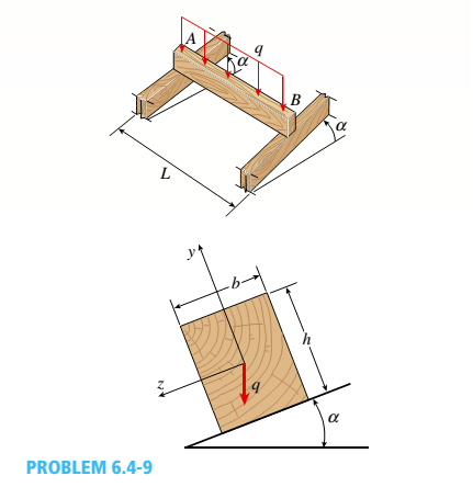
Chapter 6, Problem 6.4.9P
A wood beam AB with a rectangular cross section (4 in. × 6 in.) serving as a roof purlin is simply supported by the top chords of two adjacent roof trusses. The beam is subjected to distributed load q acting in the vertical direction through the centroid of the purlin cross section. The top chords of the trusses have a slope of = 27°. The purlin has length L =75 in. Determine the permissible distributed load q based on the allowable compressive and tensile stress in the beam eall = 2 ksi.
Expert Solution & Answer

Trending nowThis is a popular solution!

Students have asked these similar questions
Aluminum
10K
12'
Steel
A 12' long beam in supported by an aluminum hanger at
A and by a steel hanger at B. The beam carries a single
10K concentrated load. Neglect the self-weight of the
beam. Both hangers have the same original length.
Ealum = 10,000,000 psi
Esteel = 29,000,000 psi
If the load is located at midspan, and the steel hanger is
a 1/2" x 1/2" bar, what is the width of the 1/2" aluminum
bar, such that points A and B lie on the same horizontal
line?
1.
The horizontal beam is assumed to be rigid and
supports the distributed load shown. Determine the vertical
reactions at the supports. Each support consists of a wooden
post having a diameter of 120 mm and an unloaded
(original) length of 1.40 m. Take Ew = 12 GPa.
The horizontal beam is assumed to be rigid and
supports the distributed load shown. Determine the angle
of tilt of the beam after the load is applied. Each support
consists of a wooden post having a diameter of 120 mm and
an unloaded (original) length of 1.40 m. Take Ew = 12 GPa.
18 kN/m
A
B
C
1.40 m
2 m
+1m-
The floor plan of a building is shown in the Figure below. Using the Ultimate Design Load given,
(i)
Find the total load on column A.
(ii)
Determine the Maximum moment for beam A-D.
-2 m-
-4 m
-2 m
A
D
C
10 kN/m?
5 kN/m2
5 kN/m2
E
F
G
10 kN/m2
Floor Plan
-5 m
-3 m
Chapter 6 Solutions
Mechanics of Materials (MindTap Course List)
Ch. 6 - A composite beam is constructed using a steel...Ch. 6 - A wood beam is strengthened using two steel plates...Ch. 6 - A composite beam consisting of fiberglass faces...Ch. 6 - A wood beam with cross-sectional dimensions 200 mm...Ch. 6 - A hollow box beam is constructed with webs of...Ch. 6 - A r o lukI f/frm f «m t ub e of ou t sid e d ia...Ch. 6 - A beam with a guided support and 10-ft span...Ch. 6 - A plastic-lined steel pipe has the cross-sectional...Ch. 6 - The cross section of a sand wie h beam consisting...Ch. 6 - The cross section of a sandwich beam consisting of...
Ch. 6 - A bimetallic beam used in a temperature-control...Ch. 6 - A simply supported composite beam 3 m long carries...Ch. 6 - A simply supported wooden I-beam with a 12-ft span...Ch. 6 - -14 A simply supported composite beam with a 3.6 m...Ch. 6 - -15 A composite beam is constructed froma wood...Ch. 6 - A wood beam in a historic theater is reinforced...Ch. 6 - Repeat Problem 6.2-1 but now assume that the steel...Ch. 6 - Repeat Problem 6.2-17 but now use a...Ch. 6 - A sandwich beam having steel faces enclosing a...Ch. 6 - A wood beam 8 in. wide and 12 in. deep (nominal...Ch. 6 - A simple beam of span length 3.2 m carries a...Ch. 6 - A simple beam that is 18 ft long supports a...Ch. 6 - The composite beam shown in the figure is simply...Ch. 6 - The cross section of a beam made of thin strips of...Ch. 6 - Consider the preceding problem if the beam has...Ch. 6 - A simple beam thai is IS ft long supports a...Ch. 6 - The cross section of a composite beam made of...Ch. 6 - A beam is constructed of two angle sections, each...Ch. 6 - The cross section of a bimetallic strip is shown...Ch. 6 - A W 12 x 50 steel wide-flange beam and a segment...Ch. 6 - A reinforced concrete beam (see figure) is acted...Ch. 6 - A reinforced concrete T-beam (see figure) is acted...Ch. 6 - A reinforced concrete slab (see figure) is...Ch. 6 - A wood beam reinforced using two channels is...Ch. 6 - A wood beam reinforced by an aluminum channel...Ch. 6 - A beam with a rectangular cross section supports...Ch. 6 - A wood beam with a rectangular cross section (see...Ch. 6 - Solve the preceding problem for the following...Ch. 6 - A simply supported wide-flange beam of span length...Ch. 6 - Solve the preceding problem using the fol...Ch. 6 - A wood cantilever beam with a rectangular cross...Ch. 6 - Solve the preceding problem for a cantilever beam...Ch. 6 - A 2-m-long cantilever beam is constructed using a...Ch. 6 - A wood beam AB with a rectangular cross section (4...Ch. 6 - A steel beam of I-section (see figure) is simply...Ch. 6 - A cantilever beam with a wide-flange cross section...Ch. 6 - Solve the preceding problem using a W 310 x 129...Ch. 6 - A cantilever beam of W 12 × 14 section and length...Ch. 6 - A cantilever beam built up from two channel...Ch. 6 - A built-Lip I-section steel beam with channels...Ch. 6 - Repeat Problem 6.4-14 but use the configuration of...Ch. 6 - A beam with a channel section is subjected to a...Ch. 6 - A beam with a channel section is subjected to a...Ch. 6 - An angle section with equal legs is subjected to a...Ch. 6 - An angle section with equal legs is subjected to a...Ch. 6 - A beam made up all woun equal leg angles is...Ch. 6 - The Z-section of Example D-7 is subjected to M = 5...Ch. 6 - The cross section of a steel beam is constructed...Ch. 6 - The cross section of a steel beam is shown in the...Ch. 6 - A beam with a semicircular cross section of radius...Ch. 6 - .10 A built-up bourn supporting a condominium...Ch. 6 - Asteelpost (E = 30 × 106 psi) having thickness t =...Ch. 6 - A C 200 x 17.1 channel section has an angle with...Ch. 6 - A cold-formed steel section is made by folding a...Ch. 6 - A simple beam with a W 10 x 30 wide-flange cross...Ch. 6 - Solve the preceding problem for a W 250 × 44.8...Ch. 6 - A beam of wide-flange shape, W 8 x 28, has the...Ch. 6 - Solve the preceding problem for a W 200 × 41,7...Ch. 6 - Calculate the distance e from the cent crime of...Ch. 6 - Calculate the distance e from the centerline of...Ch. 6 - The cross section of an unbalanced wide-flange...Ch. 6 - The cross section of an unbalanced wide-flange...Ch. 6 - The cross section of a channel beam with double...Ch. 6 - The cross section of a slit circular tube of...Ch. 6 - The cross section of a slit square tube of...Ch. 6 - The cross section of a slit rectangular tube of...Ch. 6 - A U-shaped cross section of constant thickness is...Ch. 6 - Derive the following formula for the distance e...Ch. 6 - Derive the following formula for the distance e...Ch. 6 - The cross section of a sign post of constant...Ch. 6 - A cross section in the shape of a circular arc of...Ch. 6 - Determine the shape factor f for a cross section...Ch. 6 - (a) Determine the shape factor/for a hollow...Ch. 6 - A propped cantilever beam of length L = 54 in....Ch. 6 - A steel beam of rectangular cross section is 40 mm...Ch. 6 - .5 Calculate the shape factor j for the...Ch. 6 - Solve the preceding problem for a wide-flange beam...Ch. 6 - Determine the plastic modulus Z and shape...Ch. 6 - Prob. 6.10.8PCh. 6 - Prob. 6.10.9PCh. 6 - Prob. 6.10.10PCh. 6 - A hollow box beam with height h = 16 in,, width h...Ch. 6 - Solve the preceding problem for a box beam with...Ch. 6 - A hollow box beam with height h = 9.5 in., inside...Ch. 6 - Solve the preceding problem for a box beam with...Ch. 6 - The hollow box beam shown in the figure is...Ch. 6 - Prob. 6.10.16PCh. 6 - Prob. 6.10.17PCh. 6 - A singly symmetric beam with a T-section (see...Ch. 6 - A wide-flange beam with an unbalanced cross...Ch. 6 - .20 Determine the plastic moment Mpfor beam having...
Knowledge Booster


Learn more about
Need a deep-dive on the concept behind this application? Look no further. Learn more about this topic, mechanical-engineering and related others by exploring similar questions and additional content below.Similar questions
- Problem 1: Slab design using the ACI moment coefficients Design the continuous slab shown using the ACI moment coefficients assuming the concrete weighs 24 kN/m3 and that a service live load of 15 kN/m is to be supported. The slabs are built integrally with the end supports, which are spandrel beams. fy= 420 MPa and f'c = 28 MPa. Draw a plan and section showing all reinforcements along the slab. E 7m - 6 m + 7m --arrow_forwardFigure Q2 shows the cross section of a beam. The beam is simply supported over a span of 6 m and carries a vertical point load of 40 kN acting at its mid-span. Calculate The position of the horizontal centroidal axis of the cross-section from its bottom. The second moment area of the cross-section about the horizontal centroidal axis The maximum shear load per unit length (metre) at the lower surface of the top flangearrow_forwardDetermine the internal forces at point C (i.e. Vc. Nc, Mc) of the cantilever beam shown. Point A is fixed support 30 kN 60 kN/m 2 m A C 50 kNm 3 m 3 m Vc = +75 kN, Nc = 0, Nc = 0, Mc = +80 kN-m o Vc = -120 kN, Mc = +75 kN-m o Vc = -75 kN, Nc = 0, Mc = -90 kN-m o Vc = +75 kN, Nc = 0, Mc = -75 kN-m o None of the above o Barrow_forward
- A simply supported beam with a length of 4m is loaded with a uniform distributed load (w). The beam has a rectangular hollow section with the following dimensions: Outer Base = 150 mm OuterDepth 200 mm Inner Base = 100 mm Depth = 150 mm Inner Determine the maximum uniformly distributed load which can be applied over the entire length of the beam if the bending stress is limited to 8 Mpa. Please answer with solution and fbd. Thank you.arrow_forwardTypically, an aircraft wing is supported by a single structural spar attached to the main fuselage at the wing root as shown. This arrangement can be idealized as a cantilever beam with a loading distribution characterizing wing pressure. In general, holes are introduced to the structural members to reduce the overall weight of the wing (observe the rib sections shown in B). For the idealized beam arrangement (shown in the C), assume that the cross section of the spar is uniform and has a rectangular cross section (2" x 16"). The material is 2016-T6 Aluminum. If four 7" diameter holes are introduced to the beam (as shown in C, below), what is the maximum increase in normal stress? Ignore the effect of transverse shear. (A) (C) Wing Root (Assumed Fixed) 80 lb/in 1.8' 1.8' (B) 1.8' 9' Wing Root + 1.8' W Wing Tip Fuel Tank Wing Tip (Assumed Free)arrow_forwardA new art exhibit featuring mobile works is going up in the Holland, MI, area. One piece is shown in the figure. The 155-N uniform beam is pinned to the ground by a pivot. The beam is supported by a cable (attached to the center of the beam) to allow for each of the shoes to hang freely. Each individual shoe has a weight of 9.5-N. If one shoe is attached two-fifths of the way up the beam and another shoe is attached and three-fifths of the way up the beam, with θc = 16.5° and θb = 33.6° as shown in the figure, what is the tension in the cable, in newtons? What is the x-component of the force, in newtons, that the pivot exerts on the bottom of the beam? Use the coordinate system specified in the figure. What is the y-component of the force, in newtons, that the hinge exerts on the bottom of the beam? Use the coordinate system specified in the figure.arrow_forward
- 2. The 5 m long beam AB has two types of distributed loads, and one concentrated load as shown. Find the reactions at each end. WDR = 160 N 1.0 m WDT = 200 N WOT, +2/3 m 300 N 200 N/m 80 N/m B A 1.00 m RB 2.00 m 2.00 m RA 3. The roof truss shown has its upper chord symmetrically loaded , with a single load at its lower chord. Find the end reactions R1 and R2. 4 kN 4 kN 4 kN 4 kN- 2, kN 4 kN 2 kN 4.50 m A 24 kN RA 6 kN Rc 6 panels @ 3 m 18 marrow_forwardProblem #2: Determine the resultant load of the given uniformly varying load (UVL) or trapezoidal load as shown in the figure below. Figure: W= 20 KN/m wj=6 KN/m A B length of the base = 5 m %3Darrow_forward5. For the frame shown in the figure, determine the slope at A DA using Castigliano's Theorem. E = 29X10^3 ksi. Consider support D as fixed 12 ft 5 ft 12 k 5 ft IBC= 900 in.4 LAB= 600 in.4 ICD=600 in.4arrow_forward
- Question 5 Find the supportive force system for the cantilever beam shown pinned at C. Given data: Point load, Not yet answered P=380 N and distributed load, w=80 N/m. Marked out of 5.00 on 7 m 2 m A 5 m- 5 m- Supportive force system Ax= Ay= Сх- N Су- By= Narrow_forwardThe horizontal beam ABC shown in thefigure is supported by columns BD and CE. Thebeam is prevented from moving horizontally bythe pin support at end A. Each column is pinned atits upper end to the beam, but at the lower ends, supportD is a sliding support and support E is pinned.Both columns are solid steel bars (E = 30 x 106 psi)of square cross section with width equal to 0.625 in.A load Q acts at distance a from column BD.(a) If the distance a = 12 in., what is the criticalvalue Qcr of the load?(b) If the distance a can be varied between 0 and40 in., what is the maximum possible value ofQcr? What is the corresponding value of thedistance a?arrow_forward3. Two beams are supported as shown in the diagram below, each 150mm x 200mm x 6 meters. Beam CD is a cantilever beam carrying a uniformly distributed load of 6 KN/m freely supported on beam AB. Beam AB is freely supported on each ends. E = 13.8 GPa for both beam. Neglect the weight of the beam. a. Compute the reaction at D. b. Compute the deflection at D. c. Compute the bending stress of beam CD. 6 ka lm бт 6m 6marrow_forward
arrow_back_ios
SEE MORE QUESTIONS
arrow_forward_ios
Recommended textbooks for you
 Elements Of ElectromagneticsMechanical EngineeringISBN:9780190698614Author:Sadiku, Matthew N. O.Publisher:Oxford University Press
 Mechanics of Materials (10th Edition)Mechanical EngineeringISBN:9780134319650Author:Russell C. HibbelerPublisher:PEARSON
 Thermodynamics: An Engineering ApproachMechanical EngineeringISBN:9781259822674Author:Yunus A. Cengel Dr., Michael A. BolesPublisher:McGraw-Hill Education
 Control Systems EngineeringMechanical EngineeringISBN:9781118170519Author:Norman S. NisePublisher:WILEY
 Mechanics of Materials (MindTap Course List)Mechanical EngineeringISBN:9781337093347Author:Barry J. Goodno, James M. GerePublisher:Cengage Learning
 Engineering Mechanics: StaticsMechanical EngineeringISBN:9781118807330Author:James L. Meriam, L. G. Kraige, J. N. BoltonPublisher:WILEY
Elements Of Electromagnetics
Mechanical Engineering
ISBN:9780190698614
Author:Sadiku, Matthew N. O.
Publisher:Oxford University Press
Mechanics of Materials (10th Edition)
Mechanical Engineering
ISBN:9780134319650
Author:Russell C. Hibbeler
Publisher:PEARSON
Thermodynamics: An Engineering Approach
Mechanical Engineering
ISBN:9781259822674
Author:Yunus A. Cengel Dr., Michael A. Boles
Publisher:McGraw-Hill Education
Control Systems Engineering
Mechanical Engineering
ISBN:9781118170519
Author:Norman S. Nise
Publisher:WILEY
Mechanics of Materials (MindTap Course List)
Mechanical Engineering
ISBN:9781337093347
Author:Barry J. Goodno, James M. Gere
Publisher:Cengage Learning
Engineering Mechanics: Statics
Mechanical Engineering
ISBN:9781118807330
Author:James L. Meriam, L. G. Kraige, J. N. Bolton
Publisher:WILEY
Column buckling; Author: Amber Book;https://www.youtube.com/watch?v=AvvaCi_Nn94;License: Standard Youtube License