
Mechanics of Materials
11th Edition
ISBN: 9780137605460
Author: Russell C. Hibbeler
Publisher: Pearson Education (US)
expand_more
expand_more
format_list_bulleted
Concept explainers
Videos
Textbook Question
Chapter 6.5, Problem 111P
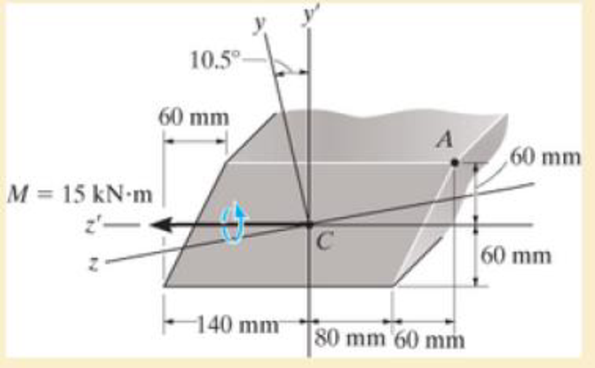
For the section, lz’ = 31.7(10-5) m4, lY’ = 114(10-5) m4, Iy,z' = -15.8(10-6) m4. Using the techniques outlined in Appendix A, the member’s cross-sectional area has principal moments of inertia of lz = 28.8(10-6) m4 and ly = 117(10-6) m4, calculated about the principal axes of inertia y and z, respectively. If the section is subjected to the moment M = 15 kN · m, determine the stress at point A using Eq. 6-17.
Expert Solution & Answer
Want to see the full answer?
Check out a sample textbook solution
Students have asked these similar questions
The cross section of a bearing block is shown in the figure by the shaded area. Calculate the moment of inertia of the section about its
base a-a.
Assume b = 11 in., h = 3 in., r = 2 in, R= 4 in.
R
a
b
Answer: lo-a = i
in.4
The cross section of a bearing block is shown in the figure by the shaded area. Calculate the moment of inertia of the section about its
base a-a.
Assume b = 29 in., h = 7 in., r = 4 in, R = 8 in.
a
Answer: la-ai
r
b
R
in.4
h
The rod BD is made of material with G1= 33 GPa has a diameter 46 mm is bonded to the tube CA at point B, the tube made of material with G2=56 GPa has an outer diameter 97 mm and wall thickness of 8 mm. If T1=1268 N.m and T2=2282 N.m, answer the following
questions:
The polar moment of inertia of the rod BD is
The polar moment of inertia of the tube CA is
The maximum shear stress of the rod BD is
The maximum shear stress of the tube CA is
The maximum shear stress of the assembly is
The angle of twist between D and B is
The angle of twist between C and A is
The angle of twist at D is
The angle of twist between C and B is
The reaction at point A is
Chapter 6 Solutions
Mechanics of Materials
Ch. 6.2 - and then draw the shear and moment diagrams for...Ch. 6.2 - In each case, express the shear and moment...Ch. 6.2 - In each case, express the shear and moment...Ch. 6.2 - In each case, express the shear and moment...Ch. 6.2 - In each case, draw the shear and moment diagrams...Ch. 6.2 - In each case, draw the shear and moment diagrams...Ch. 6.2 - In each case, draw the shear and moment diagrams...Ch. 6.2 - In each case, draw the shear and moment diagrams...Ch. 6.2 - Prob. 1PCh. 6.2 - Prob. 2P
Ch. 6.2 - Prob. 3PCh. 6.2 - Express the shear and moment in terms of x for 0 ...Ch. 6.2 - Express the internal shear and moment in the...Ch. 6.2 - Draw the shear and moment diagrams for the shaft....Ch. 6.2 - Determine the shear and moment as functions of x,...Ch. 6.2 - Determine the shear and moment as functions of x,...Ch. 6.2 - Determine the shear and moment as functions of x,...Ch. 6.2 - Determine the shear and moment in the double...Ch. 6.2 - Draw the shear and moment diagrams for the...Ch. 6.2 - Draw the shear and moment diagrams for the shaft....Ch. 6.2 - Draw the shear and moment diagrams for the...Ch. 6.2 - Draw the shear and moment diagrams for the...Ch. 6.2 - Draw the shear and moment diagrams for the...Ch. 6.2 - Prob. 16PCh. 6.2 - Draw the shear and moment diagrams for the simply...Ch. 6.2 - Prob. 19PCh. 6.2 - Draw the shear and moment diagrams for the beam.Ch. 6.2 - Draw the shear and moment diagrams for the...Ch. 6.2 - The 150-lb man sits in the center of the boat,...Ch. 6.2 - Prob. 24PCh. 6.2 - Draw the shear and moment diagrams for the beam.Ch. 6.2 - Prob. 26PCh. 6.2 - Draw the shear and moment diagrams for the beam....Ch. 6.2 - Prob. 29PCh. 6.2 - Prob. 30PCh. 6.2 - Prob. 31PCh. 6.2 - Prob. 34PCh. 6.2 - Prob. 35PCh. 6.2 - The beam is used to support a uniform load along...Ch. 6.2 - Prob. 39PCh. 6.2 - Prob. 42PCh. 6.2 - Prob. 43PCh. 6.2 - Prob. 44PCh. 6.2 - Prob. 45PCh. 6.2 - The truck is to be used to transport the concrete...Ch. 6.4 - If the beam is subjected to a bending moment of M...Ch. 6.4 - If the beam is subjected to a bending moment of M...Ch. 6.4 - If the beam is subjected to a bending moment of M...Ch. 6.4 - If the beam is subjected to a bending moment of M...Ch. 6.4 - If the beam is subjected to a bending moment of M...Ch. 6.4 - Determine the moment M that will produce a maximum...Ch. 6.4 - Determine the maximum tensile and compressive...Ch. 6.4 - The beam is constructed from four pieces of wood,...Ch. 6.4 - The beam is constructed from four pieces of wood,...Ch. 6.4 - The beam is made from three boards nailed together...Ch. 6.4 - The beam is made from three boards nailed together...Ch. 6.4 - Prob. 54PCh. 6.4 - The tubular shaft is supported by a smooth thrust...Ch. 6.4 - Prob. 57PCh. 6.4 - If the beam is subjected to an internal moment or...Ch. 6.4 - If the beam is made of material having an...Ch. 6.4 - Prob. 60PCh. 6.4 - Prob. 61PCh. 6.4 - The beam is subjected to a moment of M = 40 kN m....Ch. 6.4 - The steel shaft has a diameter of 2 in. It is...Ch. 6.4 - Determine the dimension a of a beam having a...Ch. 6.4 - A shaft is made of a polymer having an elliptical...Ch. 6.4 - Solve Prob. 6-65 if the moment M = 50 N m is...Ch. 6.4 - Prob. 67PCh. 6.4 - If M=4kipft , determine the resultant force the...Ch. 6.4 - The strut on the utility pole supports the cable...Ch. 6.4 - The pin is used to connect the three links...Ch. 6.4 - Prob. 75PCh. 6.4 - A timber beam has a cross section which is...Ch. 6.4 - If the beam is subjected to an internal moment of...Ch. 6.4 - If the allowable tensile and compressive stress...Ch. 6.4 - If the beam is subjected to an internal moment of...Ch. 6.4 - Prob. 80PCh. 6.4 - Prob. 81PCh. 6.4 - Prob. 82PCh. 6.4 - Prob. 83PCh. 6.4 - If the intensity of the load w=15kN/m , determine...Ch. 6.4 - Prob. 85PCh. 6.4 - Determine the absolute maximum bending stress in...Ch. 6.4 - Prob. 87PCh. 6.4 - Prob. 88PCh. 6.4 - If the compound beam in Prob. 642 has a square...Ch. 6.4 - If the beam in Prob. 628 has a rectangular cross...Ch. 6.4 - Determine the absolute maximum bending stress in...Ch. 6.4 - Determine, to the nearest millimeter, the smallest...Ch. 6.4 - If the beam in Prob.63 has a rectangular cross...Ch. 6.4 - The simply supported truss is subjected to the...Ch. 6.4 - If d = 450 mm, determine the absolute maximum...Ch. 6.4 - If the allowable bending stress is allow = 6 MPa,...Ch. 6.4 - Prob. 102PCh. 6.4 - Prob. 103PCh. 6.5 - Determine the bending stress at corners A and B....Ch. 6.5 - Determine the maximum bending stress in the beams...Ch. 6.5 - The member has a square cross section and is...Ch. 6.5 - The member has a square cross section and is...Ch. 6.5 - Consider the general case of a prismatic beam...Ch. 6.5 - The steel shaft is subjected to the two loads. If...Ch. 6.5 - The 65-mm-diameter steel shaft is subjected to the...Ch. 6.5 - For the section, lz = 31.7(10-5) m4, lY =...Ch. 6.5 - For the section, lz, = 31.7(10-5) m4, lY =...Ch. 6.9 - The composite beam is made of steel (A) bonded to...Ch. 6.9 - The composite beam is made of steel (A) bonded to...Ch. 6.9 - Segment A of the composite beam is made from...Ch. 6.9 - Segment A of the composite beam is made from...Ch. 6.9 - A wood beam is reinforced with steel straps at its...Ch. 6.9 - The composite beam is made of A-36 steel (A)...Ch. 6.9 - The composite beam is made of A-36 steel (A)...Ch. 6.9 - If the beam is subjected to a moment of M = 45 kN...Ch. 6.9 - The Douglas Fir beam is reinforced with A-36 steel...Ch. 6.9 - For the curved beam in Fig. 640a, show that when...Ch. 6.9 - The curved member is subjected to the moment of M...Ch. 6.9 - The curved member is made from material having an...Ch. 6.9 - If P = 3 kN, determine the bending stress at...Ch. 6.9 - If the maximum bending stress at section a-a is...Ch. 6.9 - The elbow of the pipe has an outer radius of 0.75...Ch. 6.9 - The curved bar used on a machine has a rectangular...Ch. 6.9 - The steel rod has a circular cross section. If it...Ch. 6.9 - Prob. 150PCh. 6.9 - Prob. 151PCh. 6.9 - The bar has a thickness of 1 in. and the allowable...Ch. 6.9 - The bar has a thickness of 1 in. and is subjected...Ch. 6.9 - Prob. 154PCh. 6.9 - The bar is subjected to a moment of M=17.5Nm If...Ch. 6.9 - Prob. 156PCh. 6.9 - Prob. 157PCh. 6.10 - The beam is made of an elastic plastic material...Ch. 6.10 - The wide-flange member is made from an elastic...Ch. 6.10 - The rod has a circular cross section. If it is...Ch. 6.10 - The rod has a circular cross section. If it is...Ch. 6.10 - The beam is made of an elastic perfectly plastic...Ch. 6.10 - Determine the plastic moment Mp that can be...Ch. 6.10 - Prob. 164PCh. 6.10 - Prob. 166PCh. 6.10 - Prob. 170PCh. 6.10 - Prob. 171PCh. 6.10 - The box beam is made of an elastic perfectly...Ch. 6.10 - The plexiglass bar has a stress-strain curve that...Ch. 6 - Determine the shape factor for the wide-flange...Ch. 6 - The compound beam consists of two segments that...Ch. 6 - The composite beam consists of a wood core and two...Ch. 6 - If it resists a moment of M = 125 N m, determine...Ch. 6 - Determine the maximum bending stress in the handle...Ch. 6 - The curved beam is subjected to a bending moment...Ch. 6 - Determine the shear and moment in the beam as...Ch. 6 - A wooden beam has a square cross section as shown...Ch. 6 - Draw the shear and moment diagrams for the shaft...Ch. 6 - The strut has a square cross section a by a and is...
Additional Engineering Textbook Solutions
Find more solutions based on key concepts
The spring of k and unstretched length 1.5R is attached to the disk at a radial distance of 0.75R from the cent...
Engineering Mechanics: Statics
A nozzle at A discharges water with an initial velocity of 36 ft/s at an angle with the horizontal. Determine ...
Vector Mechanics for Engineers: Dynamics
A biological fluid moves at a flow rate of m=0.02kg/s through a coiled, thin-walled, 5-mm-diameter tube submerg...
Fundamentals of Heat and Mass Transfer
3.3 It is known that a vertical force of 200 lb is required to remove the nail at C from the board. As the nail...
Vector Mechanics for Engineers: Statics, 11th Edition
23.23 A highly oxidized and uneven round bar is being turned on a lathe. Would you recommend a small or a large...
Manufacturing Engineering & Technology
CONCEPT QUESTIONS
15.CQ3 The ball rolls without slipping on the fixed surface as shown. What is the direction ...
Vector Mechanics for Engineers: Statics and Dynamics
Knowledge Booster


Learn more about
Need a deep-dive on the concept behind this application? Look no further. Learn more about this topic, mechanical-engineering and related others by exploring similar questions and additional content below.Similar questions
- ASAParrow_forwardThe cross section of a bearing block is shown in the figure by the shaded area. Calculate the moment of inertia of the section about its base a-a. Assume b = 10 in., h = 4 in., r = 2 in, R = 4 in.arrow_forwardThe cross section of a bearing block is shown in the figure by the shaded area. Calculate the moment of inertia of the section about its base a-a.Assume b = 15 in., h = 4 in., r = 2 in, R = 4 in.arrow_forward
- The cross section of a bearing block is shown in the figure by the shaded area. Calculate the moment of inertia of the section about its base a-a. Assume b-12 in., h-6 in., r-3 in, R-4 in. Answer: laa b R in.4 harrow_forwardSee Fig. P8-4. If the radius of gyration of the shaded area with respect to the y axis is r. centroidal moment of inertia I and the radius of gyration F. 8-4 -12 in. = 12.4 in., determine its A = 100 in.2 %3D C. FIGURE P8–4arrow_forwardUsing the techniques outlined in Appendix A, Example A.5 or A.6, the Z section has principal moments of inertia of I, = 0.060(10-3) mª and I; = 0.471(10-3) m*, computed about the prin- cipal axes of inertial y and z, respectively. If the section is subjected to an internal moment of M = 250 N-m directed horizontally as shown, determine the stress at point B, and the orienta- tion of the neutral axis. 50 mm 200 mm 32.9° 250 N-m 200 mm 50 mm B 50 mm -300 mmarrow_forward
- -1.50 m- -0.50 m→ Axis 0.50 m- M M Calculate the moment of inertia of the array of point objects shown in the figure (Figure 1) about the vertical axis. Assume m = 2.3 kg , M = 3.3 kg , and the objects are wired together by very light, rigid pieces of wire. The array is rectangular and is split through the middle by the horizontal axis. Calculate the moment of inertia of the array of point objects shown in the figure about the horizontal axis. Assume m = 2.3 kg , M = 3.3 kg , and the objects are wired together by very light, rigid pieces of wire. The array is rectangular and is split through the middle by the horizontal axis. С. Axisarrow_forward* For the cross section shown in the figure. Given the value of Y= 172 mm. Find the :value of total moment of Inertia 250 mm A1 Neutral Axis (N.A) A2 Ý Reference Line 50 mm 40 mm 220 mm 145.2 x 10^6 mm^4 119.7 x 10^6 mm^4 169.4 x 10^6 mm^4 129.5 x 10^6 mm^4 O 119.7 x 10^6 mm^3 O 119.7 x 10^6 mm^2 119.7 x 10^6 mm 134.2 x 10^6 mm^4 O 47.57 x 10^6 mm^4 O 193.1 x 10^6 mm^4 86.65 x 10^6 mm^4arrow_forwardThe moments and product of inertia of an L4 x 3 x 1/4-in. angle cross section with respect to two rectangular axes x and y through C are, respectively, Ix = 1.33 in4. Iy = 2.75 in4, and Ixy <0, with the minimum value of the moment of inertia of the area with respect to any axis through C being Imim = 0.692 in 4 Using Mohr’s circle, determine (a) the product of inertia Ixy of the area, (b) the orientation of the principal axes, (c) the value of Imax.arrow_forward
- A circular hole of diameter R is punched out from a circular plate of radius R shown in the figure. Find the moment of inertia about both the Y-Y axis. Say R = 90mm. %D Y X O 24134.69x10^3 mm^4 O 17558.69x10^3 mm^4 O 31132.69x10^3 mm^4 O 24554.69x10^3 mm^4arrow_forwardA symmetrical Inverted T section has the following specifications : Width of the web (W) = 100 mm,Height of the section (H) = 150 mm, Thickness of web and leg (T) = 30 mm. Determine the moment of inertia of the section with respect to the base. T= 30 mm ТОР LEG H=150mm WEB T=30 mm BASE -W = 100 mmarrow_forward5. For the cross-section below fill in the required values b. Locate the centroid of the cross section measured from the origin (O). See the figure below. X = Y == c. Determine the moment of inertia for bending about the centroidal axis parallel to the X axis. Show the axis you are finding I about on the small figure below. Ix- d. Determine the moment of inertia for bending about the centroidal axis parallel to the Y axis. Show the axis you are finding I about on the small figure below. Ty - All dimensions are in inches e. Determine the moment of inertia for bending about the X axis. Show the axis you are finding I about on the small figure below. Ix= 2" 3" 2 2 b. X = ? Draw the axis you are finding the moment of inertia about for cases b, c and d here. 111 8=? d.arrow_forward
arrow_back_ios
arrow_forward_ios
Recommended textbooks for you
 Mechanics of Materials (MindTap Course List)Mechanical EngineeringISBN:9781337093347Author:Barry J. Goodno, James M. GerePublisher:Cengage Learning
Mechanics of Materials (MindTap Course List)
Mechanical Engineering
ISBN:9781337093347
Author:Barry J. Goodno, James M. Gere
Publisher:Cengage Learning
Everything About COMBINED LOADING in 10 Minutes! Mechanics of Materials; Author: Less Boring Lectures;https://www.youtube.com/watch?v=N-PlI900hSg;License: Standard youtube license