
Concept explainers
Videos
For the network in Fig. 7.78:
a. Find currents
b. Find voltages
c. Find the power delivered to the
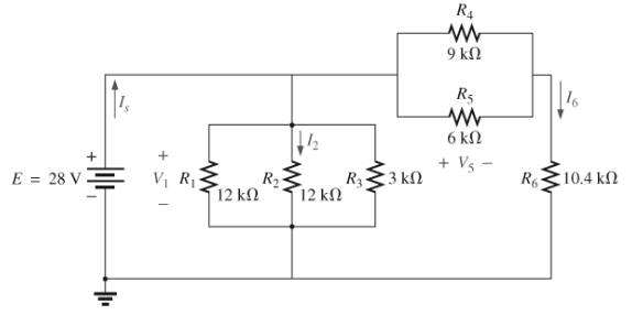
Fig. 7.78

Trending nowThis is a popular solution!

Learn your wayIncludes step-by-step video

Chapter 7 Solutions
Introductory Circuit Analysis (13th Edition)
Additional Engineering Textbook Solutions
Electrical Engineering: Principles & Applications (7th Edition)
Fundamentals of Applied Electromagnetics (7th Edition)
Starting Out With Visual Basic (7th Edition)
Starting Out with Programming Logic and Design (5th Edition) (What's New in Computer Science)
Objects First with Java: A Practical Introduction Using BlueJ (6th Edition)
Engineering Mechanics: Dynamics (14th Edition)


- Q 2) For the network in Fig. 7.64: a. Find the total resistance R, b. Find the source current I, and currents /, and Iy. c. Find current ls. d. Find voltages V; and Va. Ry R 120 40 R4 14 V V, R 120 Ryarrow_forwardCalculate the total resistance of the voltage divider circuit shown in Fig. 7-1. Rr EDN BAGLI Calculate the input line current using the indicated input voltage. MAdc $1 0-100mAde mA R1 1K R2 35Vdc 1K B R3 1.5K RL A Fig. 7-1 Calculate the voltages across resistors R1, R2 and R3. ERI Vd Er2 Era Vd Vdcarrow_forward276 ||| SERIES-PARALLEL CIRCUITS *7. For the network in Fig. 7.67: a. Find currents I, I, and l b. Find voltages V, and V c. Find the power delivered to the 3 kfl resistor *& For the series-parallel configuration in Fig. 7.68 a. Find the source current , b. Find currents, and/ e. Find current l d. Find voltage V R₁1052 80 V = R₂ W 50 +20 V 50 592 w 4 R. 3802 ww 601 R₁4 R₁80 R, 212 + FIG. 7.68 Problem 8. FIG. 7.69 Problem 9. 9. Determine the currents /, and I, for the network in Fig. 7.69. 16 1 R₂ W www 250 12. For the network in Fig. 7.72: a. Determine the current 7. b. Calculate the currents I, and 1₂. e. Determine the voltage levels V, and V 8 20V M 8,30 [+ R₂30 R, GURGU FIG. 7.72 Problem 12. 48 V E = 28 V TOV R₂40 -79 R₂ *13. Determine the de levels for the transistor network in Fig. 7.73 using the fact that Vas-0.7 V, V-2V, and Ic - Ig That is a. Determine I, and lo -1k0 114 41242² FIG. 7.66 Problem 6 FIG. 7.67 Problem 7. R, 401 1₁ ly 4,340 R₂ 10. a. Find the magnitude and…arrow_forward
- 11. For the series-parallel network of Fig. 7.59: a. Find the current I. R2 9. b. Find the currents I3 and I9. c. Find the current Ig. d. Find the voltage V. 50 V. R31 ab. R7 R,10 0 80 V R9 R4 = 42- R58N FIG. 7.59 Problem 11.arrow_forward4_59407736683332... Problem II SERIES-PARALLEL NETWORKS *21. For the network of Fig. 7.84: a. Determine the current /. b. Calculate the open-circuit voltage V *22. For the network of Fig. 7.85, find the resistance current through it is 2 A. 20 V R E120 80 120 V 18 V 60 R200 30 FIG. 7.84 Problem 21. FIG. 7.85 Problem 22arrow_forward9. For the network of Fig. 7.57: a. Determine the current I,. b. Calculate the currents I2 and I3. c. Determine the voltage levels V, and V. Eo 20 V RI3N OVa 12 R2 3 2 R432 13 R5 R3 FIG. 7.57 Problem 9.arrow_forward
- 14. For the network of Fig. 7.86, Vp = 12 V. Determine: a. Ip. b. Vs and Vps- c. Vg and VGs. d. Vp.arrow_forward*11. For the series-parallel network of Fig. 7.74: R2 R6 a. Find the current I. b. Find the currents I and Ig. c. Find the current Ig. d. Find the voltage Vab 6Ω V 19 at Ro 60 1s R1 10 Ω 80 V 4Ω R = 40 Rs8N R20 FIG. 7.74 Problem 11.arrow_forward*25. For the combination network of Fig. 7.97, determine: a. VB and VG- b. Vg. c. IE, Ic, and Ip. d. Iв- e. Vc, Vs, and Vp- f. VCE- g. VDs- 2.2 k2 40 k2 OVD Dss 6 mA Vps Vp =-6 V Va.Va Vy.Vc le VCE B = 100 10 k2 VEE 1.2 k2 FIG. 7.97 Problem 25.arrow_forward
- 6. For the circuit board in Fig. 7.66: a. Find the total resistance R, of the configuration. b. Find the current drawn from the supply if the applied voltage is 48 V. c. Find the reading of the applied voltmeter. 10 6.8 kl 1.2 k 3.3 k 2 k RT 48 V 1 k 24 kf FIG. 7.66 Problem 6.arrow_forwardQ2 o 20 V For the network of Fig. 7.85, determine: 2.2 kn a. VG- b. Ipo and VGSo c. Vp and Vs- d. Vpsg 910 k2 DO Dss = 10 mA Vp =-3.5 V VG +] Vaso 110 kΩ 1.1 k2arrow_forwardA battery with EMF of 7V and an internal resistance, r=0.08 is connected to a load resistance R=240. Determine its terminal voltage. r www + M Rarrow_forward
 Introductory Circuit Analysis (13th Edition)Electrical EngineeringISBN:9780133923605Author:Robert L. BoylestadPublisher:PEARSON
 Delmar's Standard Textbook Of ElectricityElectrical EngineeringISBN:9781337900348Author:Stephen L. HermanPublisher:Cengage Learning
 Programmable Logic ControllersElectrical EngineeringISBN:9780073373843Author:Frank D. PetruzellaPublisher:McGraw-Hill Education
 Fundamentals of Electric CircuitsElectrical EngineeringISBN:9780078028229Author:Charles K Alexander, Matthew SadikuPublisher:McGraw-Hill Education
 Electric Circuits. (11th Edition)Electrical EngineeringISBN:9780134746968Author:James W. Nilsson, Susan RiedelPublisher:PEARSON
 Engineering ElectromagneticsElectrical EngineeringISBN:9780078028151Author:Hayt, William H. (william Hart), Jr, BUCK, John A.Publisher:Mcgraw-hill Education,