
Concept explainers
Videos
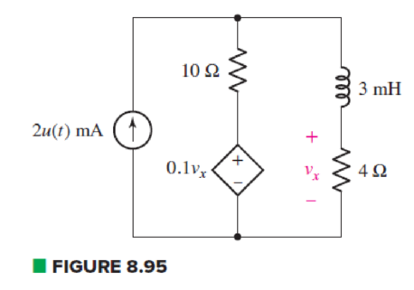
In the circuit of Fig. 8.95, a 3 mF capacitor is accidentally installed instead of the inductor. Unfortunately, that’s not the end of the problems, as it’s later determined that the real capacitor is not really well modeled by an ideal capacitor, and the dielectric has a resistance of 10 kΩ (which should be viewed as connected in parallel to the ideal capacitor). (a) Compute the circuit time constant with and without taking the dielectric resistance into account. By how much does the dielectric change your answer? (b) Calculate vx at t = 200 ms. Does the dielectric resistance affect your answer significantly? Explain.
(a)
Find the value of circuit time constant with and without taking dielectric resistance and explain the change in time constant by dielectric resistance.
Answer to Problem 77E
Value of time constant without dielectric is
Explanation of Solution
Given Data:
Value of capacitor by which the
Value of dielectric resistance is
Formula used:
The expression for resistance is as follows:
Here,
The expression for the circuit time constant is as follows:
Here,
Calculation:
To find equivalent resistance of a circuit seen by the capacitor, open circuit the inductor and replace all independent sources by their internal resistances. That is, replace current source by open circuit.
Circuit contains dependent voltage source. So to find equivalent resistance connect an arbitrary voltage source of
The circuit diagram is redrawn as shown in Figure 1.
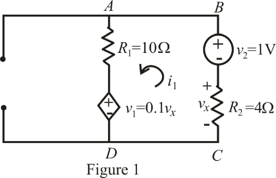
Refer to the redrawn Figure 1.
Circuit is drawn for without dielectric resistor.
The expression for Kirchhoff’s voltage law in mesh
Here,
Substitute
The expression for
Here,
Substitute
Substitute
Rearrange equation (6) for
Simplify for
Substitute
Substitute
So, value of time constant without dielectric is
To find equivalent resistance of a circuit, independent sources are replaced by their internal resistances. Therefore, replace current source by open circuit.
Circuit is containing dependent voltage source. So, to find equivalent resistance connect a voltage source of
The circuit diagram is redrawn as shown in Figure 2.
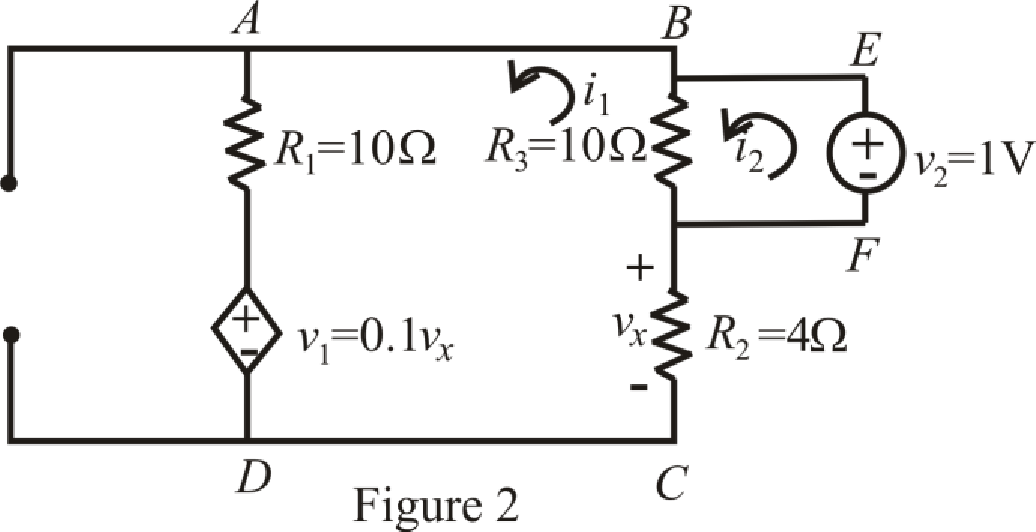
Refer to the redrawn Figure 2:
Circuit is drawn for resistor with dielectric.
The expression for KVL in mesh
Here,
The expression for KVL in mesh
Here,
Substitute
Substitute
Rearrange (10) for
Substitute
Rearrange equation (12) for
Substitute
Rearrange equation (13) for
Simplify for
Substitute
Substitute
So value of time constant with dielectric is
The expression for percentage change in time constant with dielectric resistor is as follows;
Here,
Substitute
Conclusion:
Thus, value of time constant without dielectric is
(b)
Calculate
Answer to Problem 77E
Value of voltage
Explanation of Solution
Given Data:
Value of time
Formula used:
The expression for voltage is as follows:
Here,
The expression for the final response is as follows:
Here,
The expression for current flowing through capacitor is as follows:
Here,
Calculation:
The circuit diagram is redrawn as shown in Figure 3 for
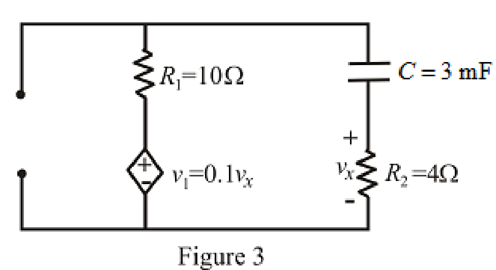
Refer to the redrawn Figure 3:
Circuit is drawn for resistor without dielectric.
As there is no independent source present in the circuit which means voltage across capacitor is also
So, value of
At
Therefore,
So,
The circuit diagram is redrawn as shown in Figure 4 for
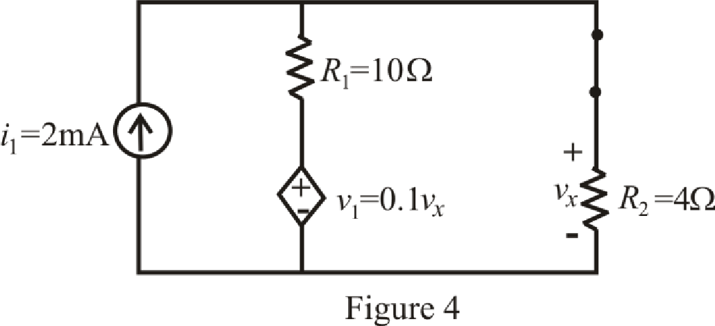
At
So, capacitor behaves as open circuit.
The circuit diagram is redrawn as shown in Figure 5 for
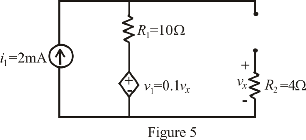
Refer to the redrawn Figure 5:
The expression for voltage
Here,
As capacitor is open circuited, current flowing through resistor
Which means value of voltage
Substitute
The circuit diagram is redrawn as shown in Figure 6 for
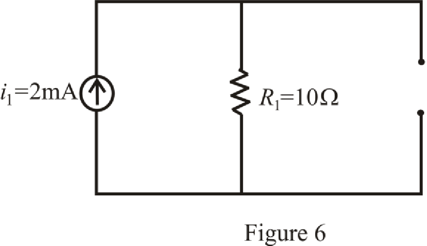
Refer to the redrawn Figure 6:
Substitute
So,
Substitute
Substitute
Substitute
The expression for voltage
Here,
Substitute
So, value of voltage
Circuit is drawn for resistor with dielectric.
The circuit diagram is redrawn as shown in Figure 7 for
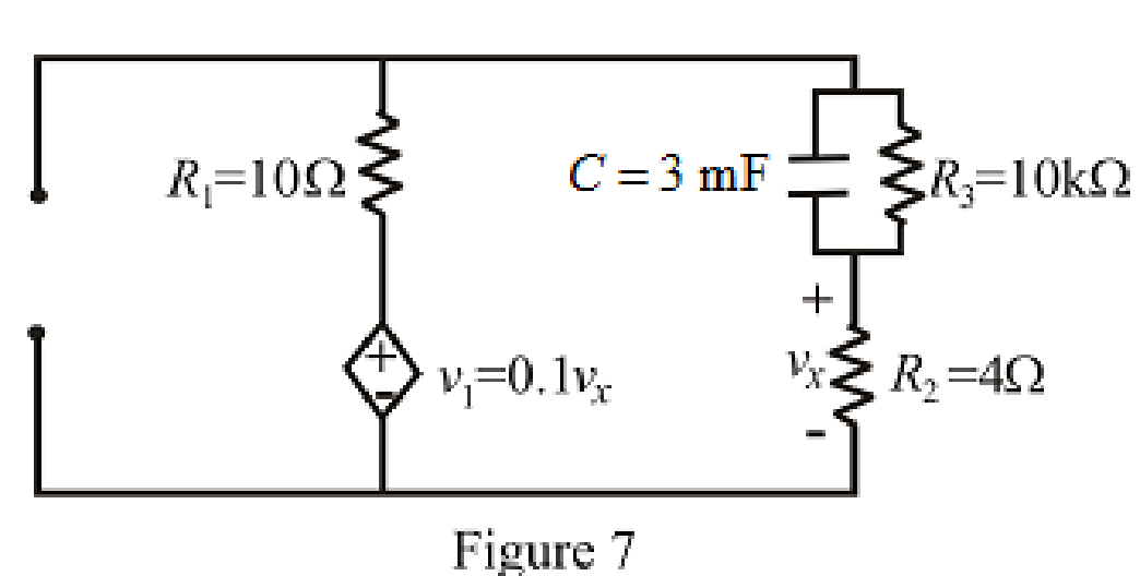
Refer to the redrawn Figure 7:
As there is no independent source present in the circuit which means voltage across capacitor is also
So, value of
At
Therefore,
So,
The circuit diagram is redrawn as shown in Figure 8for
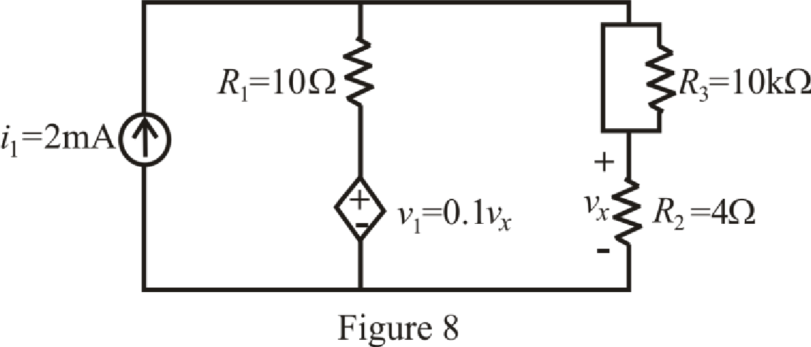
At
So, capacitor behaves as open circuit.
The circuit diagram is redrawn as shown in Figure 9 for
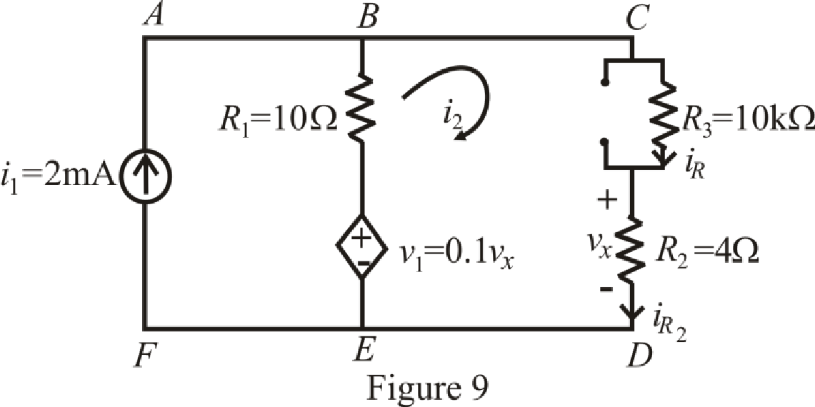
Refer to the redrawn Figure 9:
The expression for KVL in mesh
Here,
Substitute
The expression for voltage
Here,
Substitute
Substitute
Rearrange equation (24) for
Simplify for
Substitute
So,
Substitute
Substitute
Substitute
Substitute
The expression for current
Here,
Substitute
The expression for current
Here,
Substitute
The expression for voltage
Here,
Substitute
So value of voltage
The expression for percentage change in voltage
Here,
Substitute
Conclusion:
Thus, value of voltage
Want to see more full solutions like this?
Chapter 8 Solutions
Engineering Circuit Analysis

