
Find the maximum positive and negative shears and the maximum positive and negative bending moments at point C.
Answer to Problem 6P
The maximum positive shear at point C is
The maximum negative shear at point C is
The maximum positive moment at point C is
The maximum negative moment at point C is
Explanation of Solution
Given Information:
The concentrated live load (P) is 150 kN.
The uniformly distributed live load
The uniformly distributed dead load
Calculation:
Apply a 1 kN unit moving load at a distance of x from left end A.
Sketch the free body diagram of beam as shown in Figure 1.
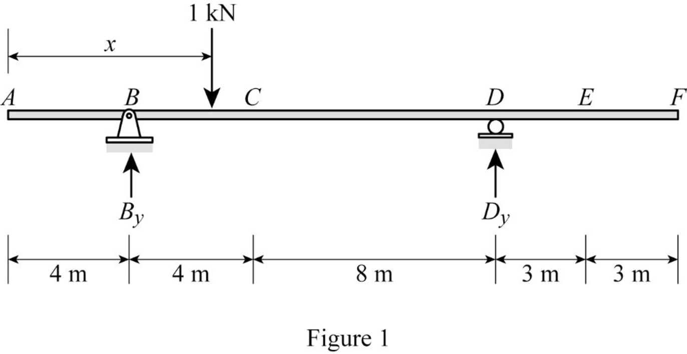
Refer Figure 1.
Find the equation of support reaction
Take moment about point D.
Consider moment equilibrium at point D.
Consider clockwise moment as positive and anticlockwise moment as negative.
Sum of moment at point D is zero.
Find the equation of support reaction
Apply vertical equilibrium equation of forces.
Consider upward force as positive
Substitute
Influence line for the shear at point C.
Apply 1 kN load at just left of C.
Find the equation of shear force at C of portion AB
Sketch the free body diagram of the section AC as shown in Figure 2.
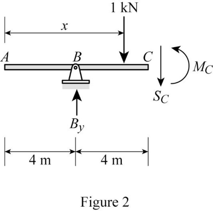
Refer Figure 2.
Apply equilibrium equation of forces.
Consider upward force as positive
Substitute
Apply 1 kN load at just right of C.
Find the equation of shear force at C of portion CF
Sketch the free body diagram of the section AC as shown in Figure 3.
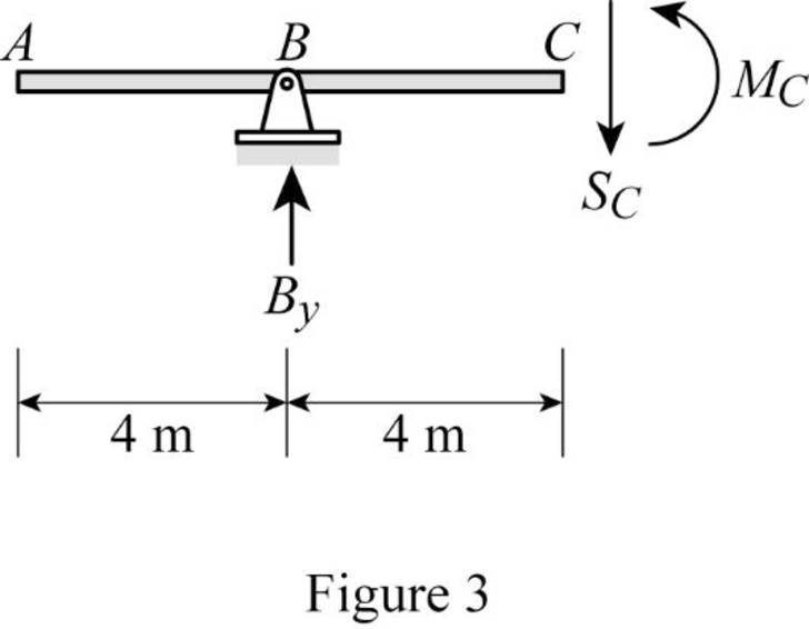
Refer Figure 3.
Apply equilibrium equation of forces.
Consider upward force as positive
Substitute
Thus, the equations of the influence line for
Find the value of influence line ordinate of shear force
| x | Position | Influence line ordinate of |
| 0 | A | |
| 4 | B | |
| 8 | ||
| 8 | ||
| 16 | D | 0 |
| 19 | E | |
| 22 | F |
Draw the influence lines for the shear force at point C using Table 1 as shown in Figure 4.
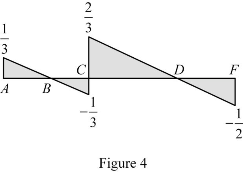
Refer Figure 4.
The maximum positive ILD ordinate at point C is
The maximum negative ILD ordinate at point C is
Find the positive area
Here,
Substitute 4 m for
Find the negative area
Here,
Substitute 4 m for
Find the maximum positive shear at point C using the equation.
Substitute 150 kN for P,
Therefore, the maximum positive shear at point C is
Find the maximum negative shear at point C using the equation.
Substitute 150 kN for P,
Therefore, the maximum negative shear at point C is
Influence line for moment at point C.
Refer Figure 2.
Consider clockwise moment as positive and anticlockwise moment as negative.
Find the equation of moment at C of portion AC
Substitute
Refer Figure 3.
Consider clockwise moment as negative and anticlockwise moment as positive.
Find the equation of moment at C of portion CF
Substitute
Thus, the equations of the influence line for
Find the value of influence line ordinate of moment
| x | Position | Influence line ordinate of |
| 0 | A | |
| 4 | B | 0 |
| 8 | ||
| 16 | D | 0 |
| 19 | E | |
| 22 | F |
Draw the influence lines for the moment at point C using Table 2 as shown in Figure 5.
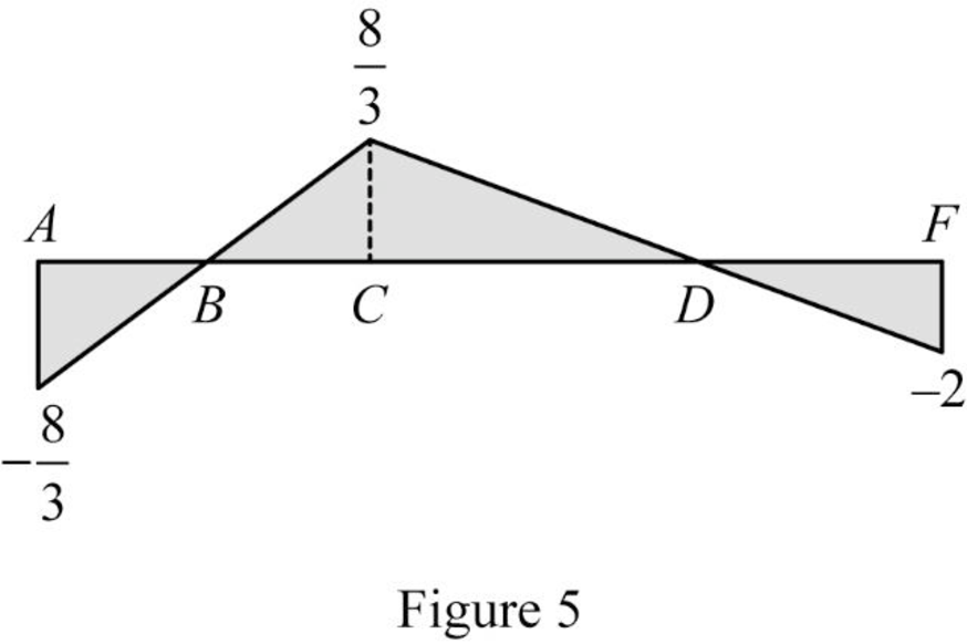
Refer Figure 5.
The maximum positive ILD ordinate of moment at C is
The maximum negative ILD ordinate of moment at C is
Find the positive area
Here,
Substitute 12 m for
Find the negative area
Substitute 4 m for
Find the maximum positive moment at point C using the equation.
Substitute 150 kN for P,
Therefore, the maximum positive moment at point C is
Find the maximum negative moment at point C using the equation.
Substitute 150 kN for P,
Therefore, the maximum negative moment at point C is
Want to see more full solutions like this?
Chapter 9 Solutions
Structural Analysis (MindTap Course List)

- The continuous beam ABC, Fig.2, is fixed at A and pinned at C with a roller support at B. The point loads of 30 KN and 20 kN act at the midpoints of AB and BC respectively. Use the method of consistent deformations to determine the reaction components and draw the shear force and bending moment diagrams for the beam. (constant EI). AH F 30 kN ↓ 12m 20 kN 12m Fig.2arrow_forwardQ.2. A beam ABC with an overhang at one end supports a uniform load of intensity 12 kN/m and a concentrated load of magnitude 2.4 kN as shown in figure (2). Draw the shear-force and bending-moment diagrams for this beam. 12 kN/m -1.6 m- H B -1.6 m- Fig. (2) 2.4 kN 1.6m icarrow_forwardProb. 4.3-13. The solid circular shaft in Fig. P4.3-13 is sub- jected to a distributed external torque that varies linearly from intensity of to per unit of length at x = 0 to zero at x = L. The shaft has a diameter d and shear modulus G and is fixed to a rigid wall at x = 0. (a) Determine an expression for the maximum (cross-sectional) shear stress in the shaft as a function of the distance x from the left end. (b) Deter- mine an expression for the total angle twist, d. at the free end. The shear modulus of elasticity is G. C to -t(x) P4.3-13 OBarrow_forward
- determine the maximum positive and negative shears and the maximum positive and negative bending moments at point C due to a concentrated live load of 150 kN, a uniformly distributed live load of 50 kN/m, and a uniformly distributed dead load of 25 kN/marrow_forwardFor the beam shown, determine the maximum positive and negative shears and the maximum positive and negative bending moments at point C due to concentrated live load of 150 kN, a uniformly distributed live load of 50 kN/m. The weight of the beam is 25kN/m. 5 m 6 m D m 4 m-arrow_forwardThe beam ABC, Fig.2, is fixed at A and roller supported at B. Use the method of consistent deformations to determine the reaction components, and draw the shear force and bending moment diagrams for the beam. (constant El) 15 kN/m MIM Fig.2 7m 7m Barrow_forward
- The rigid frame shown in Fig.1 is pinned at A and roller supported at D. For the given loading, determine the support reactions and draw the axial force, shear force and bending moment diagrams. 17.5 kN/m C 4.5 m 112 kN- B 67.5 kN 6 m 4.5 m Fig.1 9 marrow_forward4.18. Consider the balcony-type structure shown in Fig. 4-23. The horizontal balcony is loaded by a total load of 80 kN distributed in a radially symmetric fashion. The central support is a shaft 500 mm in diameter and the balcony is welded at both the upper and lower surfaces to this shaft by welds 10 mm on a side (or leg) as shown in the enlarged view at the right. Determine the average shearing stress existing between the shaft and the weld. Ans. 2.5 MPa 94 DIRECT SHEAR STRESSES [CHAP. 4 80 kN 10 mm -500 mm 10 mm Fig. 4-23 500 mmarrow_forward60 100 60 30 200 10 50 100s 2000 400 300 120 VA 12" FIG. P 2-17 6' 2-18. Determine the resultant of the parallel, coplanar force system shown in Fig. P 2-18 and locate it with respect to point A. FIG. P 2-18arrow_forward
- Draw qualitative influence lines for the bending moment and shear at point A of the building frame shown in Fig. P14.19. Also, show the arrangements of a uniformly distributed downward live load wl to cause the maximum positive bending moment at A, and the maximum negative shear at Aarrow_forward(6.70 A beam with two equal overhangs carries a unitoad between supports A and B and concentrated loads at the free ends. shown in Fig. P6.70. (a) Write an expression for distributed load, shear, and moment acting in the beam. (b) Draw shear and moment diagrams. y P=-10 KN A -1 m w = 15 kN/m 2 m Figure P6.70 P=10 KN B 123 Narrow_forwardProblem 1: The figure shown is a beam subjected to varying loadings and a point load. a) Determine the magnitude and direction of the single equivalent force to the forcina svstem shown. Specify its location on the beam from point B. b) Calculate for the support reactions at A and B. Fig. 19kN 4kN/m 7.7 kN/m A -5 m- 6.8 m 2.8knarrow_forward

 Structural Analysis (10th Edition)Civil EngineeringISBN:9780134610672Author:Russell C. HibbelerPublisher:PEARSON
 Principles of Foundation Engineering (MindTap Cou...Civil EngineeringISBN:9781337705028Author:Braja M. Das, Nagaratnam SivakuganPublisher:Cengage Learning
 Fundamentals of Structural AnalysisCivil EngineeringISBN:9780073398006Author:Kenneth M. Leet Emeritus, Chia-Ming Uang, Joel LanningPublisher:McGraw-Hill Education
 Traffic and Highway EngineeringCivil EngineeringISBN:9781305156241Author:Garber, Nicholas J.Publisher:Cengage Learning