
Mechanics of Materials
11th Edition
ISBN: 9780137605460
Author: Russell C. Hibbeler
Publisher: Pearson Education (US)
expand_more
expand_more
format_list_bulleted
Concept explainers
Videos
Textbook Question
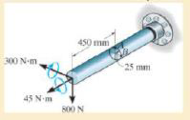
Chapter 9.5, Problem 84P
The solid shaft is subjected to a torque, bending moment, and shear force Determine the principal stresses at points A and B and the absolute maximum shear stress.
Expert Solution & Answer
Want to see the full answer?
Check out a sample textbook solution
Students have asked these similar questions
The shaft consists of three concentric tubes, each made from the same material and having inner and outer radii as given below. Length of shaft is 2m. One end is fixed to the wall and to the other end a disc is attached. If a torque of T =800 N.m is applied at the disc end, determine the maximum shear stress in the shaft. 1. Inner tube: r; = 20mm, r, = 25 mm 2. Center tube: r; = 26 mm, r. = 30 mm 3. Outer tube: r = 32mm, r, = 38mm
For the shaft shown below, determine the normal and shear stresses acting on the element located
at point A, including stress concentrations. Then draw the stress element at A with the applied
stresses and determine the three principal stress (0₁, 2 and, σ3) using Mohr's circle.
r = 0.0042 m,
d = 0.03 m,
D = 0.033 m,
T = 250 Nm
P = 1500 N, M = 300 Nm,
A
M
M
DEHRƏC
T
d
T
P
P
r
The internal loadings at a cross section through the 6-in.-diameter drive shaft of a turbine consist of an axial force of 2500 lb, a bending moment of 800 lb # ft, and a torsional moment of 1500 lb # ft. Determine the principal stresses at point B. Also calculate the maximum in-plane shear stress at this point.
Chapter 9 Solutions
Mechanics of Materials
Ch. 9.3 - Determine the normal stress and shear stress...Ch. 9.3 - Determine the equivalent state of stress on an...Ch. 9.3 - Also, find the corresponding orientation of the...Ch. 9.3 - Determine the equivalent state of stress on an...Ch. 9.3 - Determine the maximum principal stress at point B.Ch. 9.3 - Determine the principal stress at point C.Ch. 9.3 - Determine the stress components acting on the...Ch. 9.3 - Solve Prob.99 using the stress transformation...Ch. 9.3 - Determine the stress components acting on the...Ch. 9.3 - Determine the equivalent state of stress on an...
Ch. 9.3 - The stress along two planes at a point is...Ch. 9.3 - The state of stress at a point in a member is...Ch. 9.3 - The wood beam is subjected to a load of 12 kN. If...Ch. 9.3 - The internal loadings at a section of the beam are...Ch. 9.3 - Solve Prob.925 for point B. 925. The internal...Ch. 9.3 - Solve Prob.925 for point C. 925. The internal...Ch. 9.3 - It is subjected to a torque of 12 kip in. and a...Ch. 9.3 - A paper tube is formed by rolling a cardboard...Ch. 9.3 - Solve Prob.931 for the normal stress acting...Ch. 9.3 - Determine the principal stresses in the...Ch. 9.3 - The shaft has a diameter d and is subjected to the...Ch. 9.4 - Use Mohrs circle to determine the normal stress...Ch. 9.4 - Also, find the corresponding orientation of the...Ch. 9.4 - Draw Mohrs circle and determine the principal...Ch. 9.4 - Determine the principal stresses at a point on the...Ch. 9.4 - Determine the principal stresses at point A on the...Ch. 9.4 - Point A is just below the flange.Ch. 9.4 - Mohrs circle for the state of stress is shown in...Ch. 9.4 - Determine (a) the principal stresses and (b) the...Ch. 9.4 - Determine the equivalent state of stress if an...Ch. 9.4 - Draw Mohrs circle that describes each of the...Ch. 9.4 - Draw Mohrs circle trial describes each of the...Ch. 9.4 - Determine (a) the principal stresses and (b) the...Ch. 9.4 - Determine (a) the principal stresses and (b) the...Ch. 9.4 - Draw Mohrs circle that describes each of the...Ch. 9.4 - The grains of wood in the board make an angle of...Ch. 9.4 - A spherical pressure vessel has an inner radius of...Ch. 9.4 - The cylindrical pressure vessel has an inner...Ch. 9.4 - If the box wrench is subjected to the 50 lb force,...Ch. 9.4 - If the box wrench is subjected to the 50-lb force,...Ch. 9.5 - Draw the three Mohrs circles that describe each of...Ch. 9.5 - Draw the three Mohrs circles that describe the...Ch. 9.5 - Determine the principal stresses and the absolute...Ch. 9.5 - The solid shaft is subjected to a torque, bending...Ch. 9.5 - The frame is subjected to a horizontal force and...Ch. 9 - Prob. 1RPCh. 9 - The steel pipe has an inner diameter of 2.75 in....Ch. 9 - Determine the equivalent state of stress If an...Ch. 9 - The crane is used to support the 350-lb load....Ch. 9 - Determine the equivalent state of stress on an...Ch. 9 - The propeller shaft of the tugboat is subjected to...Ch. 9 - Determine the principal stresses in the box beam...Ch. 9 - Determine (a) the principal stresses and (b) the...Ch. 9 - Determine the stress components acting on the...
Knowledge Booster


Learn more about
Need a deep-dive on the concept behind this application? Look no further. Learn more about this topic, mechanical-engineering and related others by exploring similar questions and additional content below.Similar questions
- The internal loadings at a cross section through the 6-in.-diameter drive shaft of a turbine consist of an axial force of 2500 lb, a bending moment of 800 lb # ft, and a torsional moment of 1500 lb # ft. Determine the principal stresses at point A. Also calculate the maximum in-plane shear stress at this point.arrow_forwardA hollow shaft with an outside diameter of 113 mm and an inside diameter of 103 mm is subjected to both a torque of T= 6.2 kN-m and an axial tension load of P = 106 kN, as shown. Determine the normal and shear stresses at point H and show them on a stress element. y (1) Answers: Ox = i MPa, oy = i MPa, Txy = i MPa.arrow_forwardThe shaft consisting of steel andaluminum segments carries thetorques T and 2T as shown in thefigure. Find the largestallowable value of T if theallowable shear stresses are 83MPa for steel and 55 MPa foraluminum, and the angle of rotationat the free end must not exceed 6°.Use G = 83GPa for steel and 28GPa for aluminum.arrow_forward
- 6. The figure below shows the geometry and loading of segment of a crankshaft. The diameter of the upper shaft is 20mm. Determine the principal stresses and the maximum shear stress at point A, which is located on the surface of the upper shaft at the zo axis. b-80 mm Xo bz = 120 mm by- 40 mm P-LOKNarrow_forwardA steel core is bonded firmly to the copper tube (shell) to form the shaft shown. The length of the shaft is 450 mm and the end A is fixed to the wall. Take the shear modulus of steel and copper as 76 GPa and 38 GPa, respectively. The diameter of the core is 60 mm and the outer diameter of the shaft is 100 mm. Determine the maximum external torque (Tmax) so that the absolute maximum shear stress for any point H on the surface of the copper shell does not exceed 50 MPa. 450 mm A 100 mm 60 mm В Tmax =? kN · marrow_forwardThe torque shown in the figure is exerted on pulleys A, B and C. If it is known that the AB axis is solid and the BC axis is a tube with an outer diameter of 40 mm and an inner diameter of 20 mm, determine the maximum shear stress on the AB axis and on the BC axis.arrow_forward
- The handwheel shown consists of the shaft, flange, and handle. A force P = 1 kN is applied to the handle as shown. The dimensions a and b are 110 mm and 220 mm respectively. If the diameter of the shaft is 24 mm, determine the maximum normal and shearing stress in the shaft. FLANGE a SHAFT HANDLEarrow_forwarda. A solid cireular shaft of length of 3 m and diameter of 50 mm rotates at 1200 rpm by a 400 HP electric motor at its middle. It derives two machines of 150 HP and 250 HP at left and right ends of the shaft, respectively. Determine the maximum shear stress and relative displacement of the two ends of the shaft. Take G = 85 GPa.arrow_forwardThe 40-mm diameter solid shaft ACBD is supported by two bearings at A and B. Due to the transmission of power to and from the shaft, the belts of the pulleys are subjected to the tension forces shown in the figure below. 1-Draw the moment and shear diagrams on the y z and y x planes 2-Determine the location and magnitude of the maximum bending (normal) stress. Hint draw the shaft cross section at that location and think of the associated stresses. 0.050 m 300 N 0.250 m 200 N 550 N 0.250 m 400 N 150m D 0.075 marrow_forward
- 4. The shaft below is hollow from A to B and solid from B to C. Determine the maximum shear stress in the shaft. The shaft has an outer diameter of 80mm and the thickness of the wall of the hollow segment is 10mm. Please note there are two different formula for solid and hollow shaft. 4 kN-m 2 kN-marrow_forwardThe cylinder for a hydraulic press has an inside diameter of 300 mm and an outside radius of 260 mm. Find the maximum shear stress in the cylinder for an internal pressure of 280 MPa.arrow_forwardProblem 2: For the shaft shown below, determine the normal and shear stresses acting on the element located at point A, including stress concentrations. Then draw the stress element at A with the applied stresses and determine the three principal stress (0₁, 02 and, 03) using Mohr's circle. r= 0.0042 m, d = 0.03 m, D = 0.033 m, T= 250 Nm P = 1500 N, M = 300 Nm, A M T J.C₁ P r M T Di darrow_forward
arrow_back_ios
SEE MORE QUESTIONS
arrow_forward_ios
Recommended textbooks for you
 Mechanics of Materials (MindTap Course List)Mechanical EngineeringISBN:9781337093347Author:Barry J. Goodno, James M. GerePublisher:Cengage Learning
Mechanics of Materials (MindTap Course List)
Mechanical Engineering
ISBN:9781337093347
Author:Barry J. Goodno, James M. Gere
Publisher:Cengage Learning
Understanding Stress Transformation and Mohr's Circle; Author: The Efficient Engineer;https://www.youtube.com/watch?v=_DH3546mSCM;License: Standard youtube license