
Concept explainers
Videos
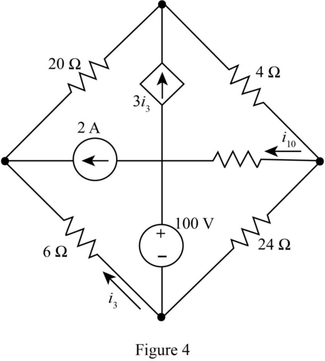
Draw a suitable tree and use general loop analysis to find i10 in the circuit of (a) Fig. A1.13a by writing just one equation with i10 as the variable; (b) Fig. A1.13b by writing just two equations with i10 and i3 as the variables.
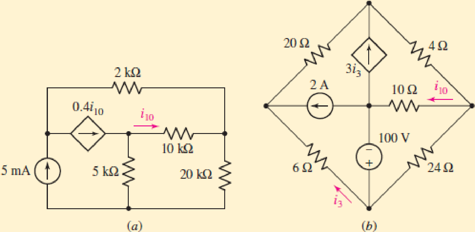
(a)
The value of the current
Answer to Problem 2P
The value of the current
Explanation of Solution
Given data:
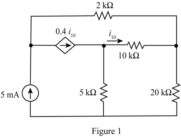
The given diagram is shown in Figure 1.
Calculation:
Draw the tree diagram of the given network.
The required diagram is shown in Figure 2.
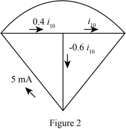
The current
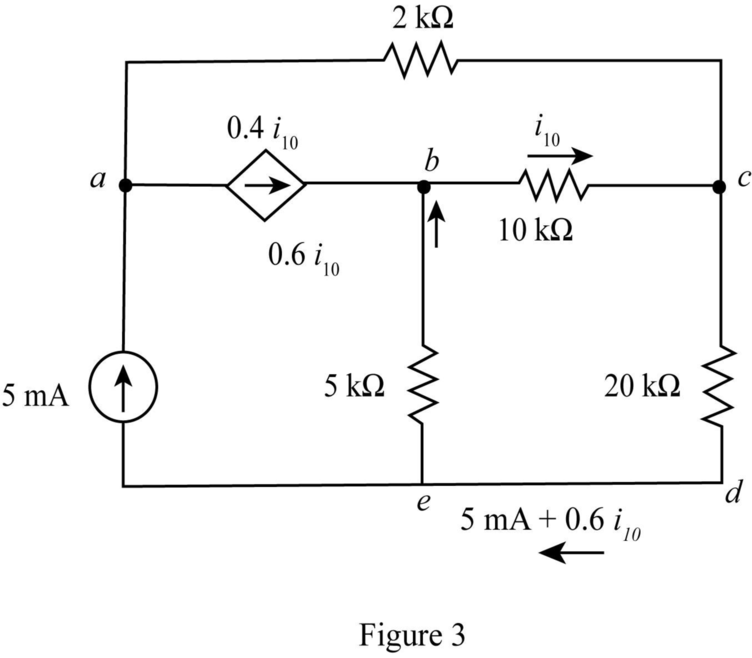
The modified diagram is shown in Figure 3.
The conversion from
The conversion from
The conversion from
The conversion from
The conversion from
The conversion from
Write the KVL for the loop
The conversion from
The conversion from
Hence, the current
Conclusion:
Therefore, the value of the current
(b)
The value of the current
Answer to Problem 2P
The value of the current
Explanation of Solution
Given data:
The given diagram is shown in Figure 4.
Calculation:
Draw tree diagram for the given network.
The required diagram is shown in Figure 5.
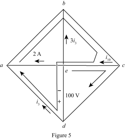
Write the KVL for the loop
Write the KVL for the loop
Substitute
Conclusion:
Therefore, the value of the current
Want to see more full solutions like this?
Chapter A1 Solutions
Loose Leaf for Engineering Circuit Analysis Format: Loose-leaf
Additional Engineering Textbook Solutions
Basic Engineering Circuit Analysis
Principles and Applications of Electrical Engineering
ELECTRICITY FOR TRADES (LOOSELEAF)
Microelectronics: Circuit Analysis and Design
Electronics Fundamentals: Circuits, Devices & Applications
Electric Circuits. (11th Edition)


- a) Draw and explain the equivalent circuit and V-I characteristics of the UJT in detail. b) A UJT circuit is shown in figure 2. The parameters of the UJT are n = 0.65 and RBB = 7 km. i. Find RBI and RB2. ii. Determine the value of VB1B2 and Vp. R₂ R₂ 400 £2 B₂ 20 100 £2 Figure 2arrow_forwardP2.28 A multiple-loop model of an urban ecological system might include the following variables: number of people in the city (P), modernization (M), migration into the city (C), sanitation facilities (S), number of diseases (D), bacteria/area (B), and amount of garbage/area (G), where the symbol for the variable is given in parentheses. The following causal loops are hypothesized: 1. P → G → B → D → P 2. Р — М —С + Р 3. Р — М —S + D-> P 4. Р > М —S> В — D-Р Sketch a signal-flow graph for these causal relationships, using appropriate gain symbols. Indicate whether you believe each gain transmission is positive or - negative. For example, the causal link S to B is negative because improved sanitation facilities lead to reduced bacteria/area. Which of the four loops are positive feedback loops and which are negative feedback loops?arrow_forward1. ) Minimize the following DFA using a. Huffman algorithm using Distinct table. For each step draw a separate Distinct table. 0, 1 1 q1 q2 q4 qo 93 1 95 1. 1.arrow_forward
- 2. Perform the following analysis and calculations on the circuit shown below. Use Kirchhoff's Laws to solve for the unknown currents I1, l2, and Ig. Show ALL calculations! a. To obtain credit, you must label all active and passive device polarities in the diagram, label each loop (and loop direction) you are using. b. To obtain credit, you must show all relevant equations using Kirchhoff's Laws. c. To obtain credit, you must show your system of linear equations in the unknown currents, and clearly demonstrate your matrix method for solving this system of equations. d. For each of the calculations, you must keep 4 digits in your final results for the currents. 40 Ω 15 Volts www. 25 0 WWw 35 Ω 12 Voltsarrow_forwardGiven, A=5 B=2 c=4 Given circuit Diagram R₁= AA.C2 = 55.4-2 52.42 R2 = AB.C 223 R3 = BCA = 24.52 R4 CA.B 2 $ 45.22 RS = AC-BR 54-2-2 R6 = BA. C 22 ⇒ 25-4-2 42052 R7= (BAR X = 2 AB V ⇒ 25.2 V I = 0 BCA 0.245 Aarrow_forwardD1 D2 F1 50 V 50 V G 10_AMP D3 D4 T1 V1 220 Vrms 60 Hz 0° (R1 $10ka 50 V 50 V 18.33 S1 Key = A 1. Identify the components used in the given circuit. Describe briefly the use(s) of these components/devices in the circuit. NOTE: turns ratio of T1 = 18.33 2. What are the voltages across the following points if a multi-tester set at 600V AC range is connected at these points? (a) AB: (b) CD: (c) EF: (d) GH: 3. What are the voltages across the following points if a multi-tester set at 600V DC range is connected at these points? (a) AB: (b) CD: (c) EF: (d) GH: NOTE: Vdc for HW rectifier = 0.318 * Vpeak = 0.45 * Vrmsarrow_forward
- The statements given below in terms of linearity, time invariance and causality your classarrow_forwardHome work: Rs Q1) For the following circuit, calculate the: 8k a) Current in resistor R1 through Rg. R125k 90VT b) Voltage between points (x) and (a), Vxa- R22k R4 R61k R71k c) Voltage between points (a) and (b), V ab [Ans: b) 39.375V, c) -22.375V] a R310k 90k R8 36.5k barrow_forwardShit AltGr Ctrl Q3) For the electrical circuit shown, construct the analogous mechanical circuit. Prove that they are analogous mathematically. C R SHOT ON MI 6 MI DUAL CAMERAarrow_forward
- (b) A system is having a zero-pole plot as shown in Fig. 2. Determine the differential equation to represent the system. Im Re Fig. 2: Zero-pole plot of a system.arrow_forward(1) Whats X *Outcom X Shopping X Pick Your X chegg pr x Chegg.cc X Electrical X bartleby x My ques X PDF File | C:/Users/Brenda/Downloads/Outcome%20A%20test%2011032021_protected.pdf Q (D Page view A Read aloud V Draw E Highlight of 6 Erase R2 → I2 Vin R1 R1 LED 4なa Outcome A test 110..pdf check1 (1).png Show all Open file Open file 11:21 O Type here to search 后 の ENG 2021/03/12 21arrow_forwardThe network shown in Figure 1.39 contains a voltage source without a series resistor. (a.) Apply the E-shift operation to the network and reduce it to a network with a single mesh or cireuit. (b.) Use the reduced network to caleulate the values for the node-to-ground voltages Va and V, without the use of the nodal analysis method. 2.50 R, R3 V, R, 60 18V 120 Rarrow_forward
 Introductory Circuit Analysis (13th Edition)Electrical EngineeringISBN:9780133923605Author:Robert L. BoylestadPublisher:PEARSON
 Delmar's Standard Textbook Of ElectricityElectrical EngineeringISBN:9781337900348Author:Stephen L. HermanPublisher:Cengage Learning
 Programmable Logic ControllersElectrical EngineeringISBN:9780073373843Author:Frank D. PetruzellaPublisher:McGraw-Hill Education
 Fundamentals of Electric CircuitsElectrical EngineeringISBN:9780078028229Author:Charles K Alexander, Matthew SadikuPublisher:McGraw-Hill Education
 Electric Circuits. (11th Edition)Electrical EngineeringISBN:9780134746968Author:James W. Nilsson, Susan RiedelPublisher:PEARSON
 Engineering ElectromagneticsElectrical EngineeringISBN:9780078028151Author:Hayt, William H. (william Hart), Jr, BUCK, John A.Publisher:Mcgraw-hill Education,