
Loose Leaf for Engineering Circuit Analysis Format: Loose-leaf
9th Edition
ISBN: 9781259989452
Author: Hayt
Publisher: Mcgraw Hill Publishers
expand_more
expand_more
format_list_bulleted
Videos
Textbook Question
Chapter 16, Problem 10E
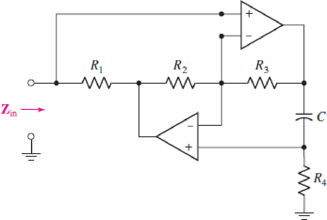
(a) If both the op amps shown in the circuit of Fig. 16.39 are assumed to be ideal (Ri = ∞, Ro = 0, and A = ∞), find Zin. (b) R1 = 4 kΩ, R2 = 10 kΩ, R3 = 10 kΩ, R4 = 1 kΩ, and C = 200 pF; show that Zin = jωLin, where Lin = 0.8 mH.
Expert Solution & Answer
Want to see the full answer?
Check out a sample textbook solution
Students have asked these similar questions
5. Find the Vout for the circuit shown below.
R1
R2
10kohm
2kohm
U1
V1
R3
15V
4kohm
OPAMP 3T_VIRTUAL
R4
V3
Vout
V2
Skohm
4V
8V
|Q2): The N-bit DAC with an (R-2R) ladder network is to be designed as a 6-bit
DAC device. Let (VREF= -5 V and R=R;=5 k2).
(a)What are currents (I, I2, 13, la, Is, and I6)?
(b)The input changes by 1 LSB. What is the change in the output voltage?
(c) What is the output voltage if the input is (010011)?
(d)What is the change in output voltage if the input changes from (101010 to
010101)?
Calculate the inductance of
L4 in the Owen bridge circuit
shown below. Given that R2 =
2002, R310 02, R4 = 5 KQ2, C1
= 10 uF.
R₂
OOC
mu
R3
La
STus-mm
R₂
COO
O2mH
1 mH
5 mH
C 10 mH
4 mH
Calculate the natural
frequency in (rad/sec) of the
Wien Bridge Oscillator circuit
shown below, Given that C3
= 10 μF, C4 = 25 μF, R3 = 10
K2, R4 = 4 KQ,
R₂
R₂
ww
0 0 0 0 0
Vref
C3
www
Vref
0.306 V
0.402 V
0.603 V
0.242 V
O 1.206 V
www
CAL
Imm
R₂
20
125
5
10
75
For the instrumentation
amplifier shown below, given
that: R1 = 500 KQ. R2 = 5 KQ.
R34 KQ2. R4 12 k2. Vi2 - Vil
=
- 2 millivolt. Calculate the
output voltage Vo:
www
Inpets
R₂+6₂
Output
Vo
Vo
Oudpen
Chapter 16 Solutions
Loose Leaf for Engineering Circuit Analysis Format: Loose-leaf
Ch. 16.1 - Find the input impedance of the network shown in...Ch. 16.1 - Write a set of nodal equations for the circuit of...Ch. 16.2 - By applying the appropriate 1 V sources and short...Ch. 16.2 - Prob. 4PCh. 16.2 - Prob. 5PCh. 16.3 - Prob. 6PCh. 16.3 - Use Y and Y transformations to determine Rin for...Ch. 16.4 - Find z for the two-port shown in (a) Fig. 16.23a;...Ch. 16.4 - Prob. 9PCh. 16.5 - Prob. 10P
Ch. 16.5 - Prob. 11PCh. 16.6 - Prob. 12PCh. 16 - For the following system of equations, (a) write...Ch. 16 - With regard to the passive network depicted in...Ch. 16 - Determine the input impedance of the network shown...Ch. 16 - For the one-port network represented schematically...Ch. 16 - Prob. 6ECh. 16 - Prob. 7ECh. 16 - Prob. 8ECh. 16 - Prob. 9ECh. 16 - (a) If both the op amps shown in the circuit of...Ch. 16 - Prob. 11ECh. 16 - Prob. 12ECh. 16 - Prob. 13ECh. 16 - Prob. 14ECh. 16 - Prob. 15ECh. 16 - Prob. 16ECh. 16 - Prob. 17ECh. 16 - Prob. 18ECh. 16 - Prob. 19ECh. 16 - Prob. 20ECh. 16 - For the two-port displayed in Fig. 16.49, (a)...Ch. 16 - Prob. 22ECh. 16 - Determine the input impedance Zin of the one-port...Ch. 16 - Determine the input impedance Zin of the one-port...Ch. 16 - Employ Y conversion techniques as appropriate to...Ch. 16 - Prob. 26ECh. 16 - Prob. 27ECh. 16 - Prob. 28ECh. 16 - Compute the three parameter values necessary to...Ch. 16 - It is possible to construct an alternative...Ch. 16 - Prob. 31ECh. 16 - Prob. 32ECh. 16 - Prob. 33ECh. 16 - Prob. 34ECh. 16 - The two-port networks of Fig. 16.50 are connected...Ch. 16 - Prob. 36ECh. 16 - Prob. 37ECh. 16 - Obtain both the impedance and admittance...Ch. 16 - Prob. 39ECh. 16 - Determine the h parameters which describe the...Ch. 16 - Prob. 41ECh. 16 - Prob. 42ECh. 16 - Prob. 43ECh. 16 - Prob. 44ECh. 16 - Prob. 45ECh. 16 - Prob. 46ECh. 16 - Prob. 47ECh. 16 - Prob. 48ECh. 16 - Prob. 49ECh. 16 - Prob. 50ECh. 16 - (a) Employ suitably written mesh equations to...Ch. 16 - Prob. 52ECh. 16 - Prob. 53ECh. 16 - The two-port of Fig. 16.65 can be viewed as three...Ch. 16 - Consider the two separate two-ports of Fig. 16.61....Ch. 16 - Prob. 56ECh. 16 - Prob. 57ECh. 16 - Prob. 58ECh. 16 - (a) Obtain y, z, h, and t parameters for the...Ch. 16 - Four networks, each identical to the one depicted...Ch. 16 - A cascaded 12-element network is formed using four...Ch. 16 - Prob. 62ECh. 16 - Continuing from Exercise 62, the behavior of a ray...
Additional Engineering Textbook Solutions
Find more solutions based on key concepts
Write the nodal equations for the network of Fig. 8.137 using the general approach. Find the nodal voltages usi...
Introductory Circuit Analysis (13th Edition)
Electric power systems provide energy in a variety of commercial and industrial settings. Make a list of system...
Principles and Applications of Electrical Engineering
The current source in the circuit shown generates the current pulse
Find (a) v (0); (b) the instant of time gr...
Electric Circuits. (11th Edition)
The voltage source of the circuit shown in Fig. P1.29 is given by s(t)=25cos(4104t45)(V). Obtain an expression ...
Fundamentals of Applied Electromagnetics (7th Edition)
When travelers from the USA and Canada visit Europe, they encounter a different power distribution system. Wall...
Electric machinery fundamentals
For the “tank” circuit in Fig. 14.79, find the resonant frequency.
Figure 14.79
For Probs. 14.39, 14.71, and 1...
Fundamentals of Electric Circuits
Knowledge Booster


Learn more about
Need a deep-dive on the concept behind this application? Look no further. Learn more about this topic, electrical-engineering and related others by exploring similar questions and additional content below.Similar questions
- (c) Find the closed-loop transfer function, C(s)/R(s) for the system shown in Figure Q3 using block diagram reduction if H1 and H2 equal to your second last and last numbers of your matric card (Example: Matrix no CD190257, H1=5, H2=7). R(s) G1 G2 H2 H1 Figure Q3arrow_forwardQ3 (a) Consider the transfer function system below. s2 + 4s + 6 Y(s) U(s) s3 + 6s2 + 4s + 2 Obtain a state-space representation of this system showing all intermediate steps. Briefly describe the characteristics of signal flow diagrams, and explain how you convert the state equations of a system (for example, a system like in part (a)) into a signal flow diagram. (b) It is required to design a state-feedback controller for the system defined in part (a) with the desired closed-loop poles at: (c) s = -1+ 2j; s = -5 Determine the gain values of the state feedback vector for this design.arrow_forwardGiven the following N-channel enhancement MOSFET circuit 1.5 MQ R2 75 k2 Rp D Vop 10 V I M2 39 k2 Rs The data are VGSTH =1 V and k= 0.0125 mA / V. %3D %3D 1) The correct quadratic equation for solving VGs is i) 0.4875VGS-0.025VGS- 3.5125 = 0 ii) 0.4875VGS + 0.025VGS - 3.5125 = 0 0.4875Ves- 1.975Ves- 3.5125 = 0 iv) 0.4875Ves + 1.975Ves - 4.4875 = 0 iii) 2) Ip is 34.39 µA 172.05 µA 19.36 µA 68.78 µA ii) 111 iv) 3) Vos is i) ii) ii) iv) 2.16 V 8.76 V 6.08 V 7.52 Varrow_forward
- Electrical Engineering Write the equations for small-signal ac dynamic model of buck-converier and defive the following iL(s) (ii) Din(s)lāt)=0 Do(s)| transfer functions, (i) a(s) Din(t)=0arrow_forwardQ1. A simplified version of an automobile or motorcycle suspension system as shown in Figure Q1. Obtain the transfer function Y(s)/U(s) of the system. The input u is a displacement input. m₂ www m₁ ww ü b i Figure Q1arrow_forwardQUESTION 4 Consider a linear circuit having input voltage Vin (t) and a corresponding output voltage Vout (t). Which of the following statements concerning time varying input and output is certainly true: a) When the input is exponential Vin(t) = e³₁t with some value $₁, the output must also be exponential Vout(t) = Aes2t with S₂ and s₁ being different in general. b) When the input is exponential Vin(t) = es₁t with exponential constant S₁, the output must also be exponential Vout (t) = = AeS₁t only if s₁is a real number, while A could be either real or complex number. c) When the input is exponential Vin(t) = es₁t with some exponential constant S₁, the output must also be exponential Vout (t) = AeS₁t, where both s₁ and A can be real or complex numbers d) None of the above a)arrow_forward
- 团 0 2.pdf Using inverting, non-inverting, Buffer, or Summer op_amps circuit to design the following equation Vo = 8 Vịarrow_forwardQ2 Show that any signal can be decomposed into an even and an odd component. Is the decomposition unique? Illustrate your arguments using the signal x{n) = {2. 3, 4. 5. 6} 1 Add Filearrow_forwarda. Asystem is provided in Block Diagram form as shown in figure 4, draw its equivalent system in Signal Flow Graph form. H3 G4 + R(s) G5 Y(s) G1 G2 G3 H1 H2 Fig 4arrow_forward
- Q4/ for the following figure : a) write the difference equation b) find h(n) X(n) y(n)arrow_forwardQ2): The N-bit DAC with an (R-2R) ladder network is to be designed as a 6-bit DAC device. Let (VREF= -5 V and R=RF=5 k2). (a) What are currents (I1, I2, l3, 14, I5, and I6)? (b) The input changes by 1 LSB. What is the change in the output voltage? (c) What is the output voltage if the input is (010011)? (d)What is the change in output voltage if the input changes from (101010 to 010101)?arrow_forwardConsider the RLC circuit shown below; write state equations, ONLY R1 / 1 Ohm LE C1/1F R3 / 1 Ohm R2/1 Ohm C2/1F 2 H/Vo X1 = Vel X₂ = Vc2 X3 = İLarrow_forward
arrow_back_ios
SEE MORE QUESTIONS
arrow_forward_ios
Recommended textbooks for you
 Introductory Circuit Analysis (13th Edition)Electrical EngineeringISBN:9780133923605Author:Robert L. BoylestadPublisher:PEARSON
 Delmar's Standard Textbook Of ElectricityElectrical EngineeringISBN:9781337900348Author:Stephen L. HermanPublisher:Cengage Learning
 Programmable Logic ControllersElectrical EngineeringISBN:9780073373843Author:Frank D. PetruzellaPublisher:McGraw-Hill Education
 Fundamentals of Electric CircuitsElectrical EngineeringISBN:9780078028229Author:Charles K Alexander, Matthew SadikuPublisher:McGraw-Hill Education
 Electric Circuits. (11th Edition)Electrical EngineeringISBN:9780134746968Author:James W. Nilsson, Susan RiedelPublisher:PEARSON
 Engineering ElectromagneticsElectrical EngineeringISBN:9780078028151Author:Hayt, William H. (william Hart), Jr, BUCK, John A.Publisher:Mcgraw-hill Education,
Introductory Circuit Analysis (13th Edition)
Electrical Engineering
ISBN:9780133923605
Author:Robert L. Boylestad
Publisher:PEARSON
Delmar's Standard Textbook Of Electricity
Electrical Engineering
ISBN:9781337900348
Author:Stephen L. Herman
Publisher:Cengage Learning
Programmable Logic Controllers
Electrical Engineering
ISBN:9780073373843
Author:Frank D. Petruzella
Publisher:McGraw-Hill Education
Fundamentals of Electric Circuits
Electrical Engineering
ISBN:9780078028229
Author:Charles K Alexander, Matthew Sadiku
Publisher:McGraw-Hill Education
Electric Circuits. (11th Edition)
Electrical Engineering
ISBN:9780134746968
Author:James W. Nilsson, Susan Riedel
Publisher:PEARSON
Engineering Electromagnetics
Electrical Engineering
ISBN:9780078028151
Author:Hayt, William H. (william Hart), Jr, BUCK, John A.
Publisher:Mcgraw-hill Education,
Routh Hurwitz Stability Criterion Basic Worked Example; Author: The Complete Guide to Everything;https://www.youtube.com/watch?v=CzzsR5FT-8U;License: Standard Youtube License