
Loose Leaf for Engineering Circuit Analysis Format: Loose-leaf
9th Edition
ISBN: 9781259989452
Author: Hayt
Publisher: Mcgraw Hill Publishers
expand_more
expand_more
format_list_bulleted
Videos
Textbook Question
Chapter 16, Problem 3E
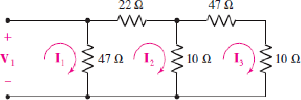
With regard to the passive network depicted in Fig. 16.33, (a) obtain the three mesh equations; (b) compute ΔZ; and (c) calculate the input impedance.
Expert Solution & Answer
Want to see the full answer?
Check out a sample textbook solution
Students have asked these similar questions
16. The resistor value of Norton equivalent, RN, for the circuit in Fig. 15, is
102
ww
20 2
0.5%,
(a) 62
(b) 5.22
(c) 4.12
(d) 3.332
digital ckts.
Q.2. Realize the following functions using minimum
number of components to draw their digital circuits.
1.
AB+ABAB
2 ABC + ABE + ABC
3. (A + B) (A + B)
4. (A+B+C). (A + 5 + c) (A + 3+C)
Home Work
• 1. Do a, d-g in the problem below :
For the network of Fig. 16.73:
*a. Find the total impedance "seen" by the source.
b. Using the results of part (a), find the total admittance.
c. Sketch the admittance diagram for the parallel network.
d. Determine the source current Is.
e. Calculate the current through the capacitive element Ic.
f. Write the sinusoidal expressions for the applied voltage
and source current.
g. What is the power factor of the network? Is it leading or
lagging? Is this considered a capacitive or inductive
configuration?
R2
40 2
R1
220 N
EA) 12 V 0°
120 N
X 60 N
FIG. 16.73
Chapter 16 Solutions
Loose Leaf for Engineering Circuit Analysis Format: Loose-leaf
Ch. 16.1 - Find the input impedance of the network shown in...Ch. 16.1 - Write a set of nodal equations for the circuit of...Ch. 16.2 - By applying the appropriate 1 V sources and short...Ch. 16.2 - Prob. 4PCh. 16.2 - Prob. 5PCh. 16.3 - Prob. 6PCh. 16.3 - Use Y and Y transformations to determine Rin for...Ch. 16.4 - Find z for the two-port shown in (a) Fig. 16.23a;...Ch. 16.4 - Prob. 9PCh. 16.5 - Prob. 10P
Ch. 16.5 - Prob. 11PCh. 16.6 - Prob. 12PCh. 16 - For the following system of equations, (a) write...Ch. 16 - With regard to the passive network depicted in...Ch. 16 - Determine the input impedance of the network shown...Ch. 16 - For the one-port network represented schematically...Ch. 16 - Prob. 6ECh. 16 - Prob. 7ECh. 16 - Prob. 8ECh. 16 - Prob. 9ECh. 16 - (a) If both the op amps shown in the circuit of...Ch. 16 - Prob. 11ECh. 16 - Prob. 12ECh. 16 - Prob. 13ECh. 16 - Prob. 14ECh. 16 - Prob. 15ECh. 16 - Prob. 16ECh. 16 - Prob. 17ECh. 16 - Prob. 18ECh. 16 - Prob. 19ECh. 16 - Prob. 20ECh. 16 - For the two-port displayed in Fig. 16.49, (a)...Ch. 16 - Prob. 22ECh. 16 - Determine the input impedance Zin of the one-port...Ch. 16 - Determine the input impedance Zin of the one-port...Ch. 16 - Employ Y conversion techniques as appropriate to...Ch. 16 - Prob. 26ECh. 16 - Prob. 27ECh. 16 - Prob. 28ECh. 16 - Compute the three parameter values necessary to...Ch. 16 - It is possible to construct an alternative...Ch. 16 - Prob. 31ECh. 16 - Prob. 32ECh. 16 - Prob. 33ECh. 16 - Prob. 34ECh. 16 - The two-port networks of Fig. 16.50 are connected...Ch. 16 - Prob. 36ECh. 16 - Prob. 37ECh. 16 - Obtain both the impedance and admittance...Ch. 16 - Prob. 39ECh. 16 - Determine the h parameters which describe the...Ch. 16 - Prob. 41ECh. 16 - Prob. 42ECh. 16 - Prob. 43ECh. 16 - Prob. 44ECh. 16 - Prob. 45ECh. 16 - Prob. 46ECh. 16 - Prob. 47ECh. 16 - Prob. 48ECh. 16 - Prob. 49ECh. 16 - Prob. 50ECh. 16 - (a) Employ suitably written mesh equations to...Ch. 16 - Prob. 52ECh. 16 - Prob. 53ECh. 16 - The two-port of Fig. 16.65 can be viewed as three...Ch. 16 - Consider the two separate two-ports of Fig. 16.61....Ch. 16 - Prob. 56ECh. 16 - Prob. 57ECh. 16 - Prob. 58ECh. 16 - (a) Obtain y, z, h, and t parameters for the...Ch. 16 - Four networks, each identical to the one depicted...Ch. 16 - A cascaded 12-element network is formed using four...Ch. 16 - Prob. 62ECh. 16 - Continuing from Exercise 62, the behavior of a ray...
Additional Engineering Textbook Solutions
Find more solutions based on key concepts
Analog Voltmeter Design Figure P2-98(a) shows a voltmeter circuit consisting of a D'Arsonval meter, two series ...
ANALYSIS+DESIGN OF LINEAR CIRCUITS(LL)
Assume a telephone signal travels through a cable at two-thirds the speed of light. How long does it take the s...
Electric Circuits (10th Edition)
Write the nodal equations for the network of Fig. 8.137 using the general approach. Find the nodal voltages usi...
Introductory Circuit Analysis (13th Edition)
The current source in the circuit shown generates the current pulse
Find (a) v (0); (b) the instant of time gr...
Electric Circuits. (11th Edition)
Electric power systems provide energy in a variety of commercial and industrial settings. Make a list of system...
Principles and Applications of Electrical Engineering
Identify the type of input and output configuration for each diff-amp in Figure 18-35.
Electronics Fundamentals: Circuits, Devices & Applications
Knowledge Booster


Learn more about
Need a deep-dive on the concept behind this application? Look no further. Learn more about this topic, electrical-engineering and related others by exploring similar questions and additional content below.Similar questions
- Given the voltage and current shown in Fig. 16.70, find the parallel network internal to the container. That is, find the actual value of each component using the provided frequency.arrow_forwardTranslate News Maps YouTube Gmail M .JI d55 /12 u vx in the circuit shown in Fig. 4 equal to : 12448-Fig. 4.pdf A. 1.148 V В. 0.248 V C. 0.258 V D. 0.148 Varrow_forward2- For the network of Fig. 16.44: a. Find the current I₁. b. Calculate the voltage Veusing the voltage divider rule. c. Find the voltage Vad E 120 V 60° R₁302 402 XL₂ Xc13 Ve X1₂ 752arrow_forward
- Q4. Use a Karnaugh map to minimize the following standard SOP expression: (15 M) ABC + ABC + ABC + ABC + ABC Q5. Plot the corresponding SUM and CARRY outputs of half-adder circuit, for the given A and B inputs. And give the logical expression for both. (15 M) HA A Barrow_forwardUse Node-Voltage Method to find the voltage v_1. V, 20 40 V 202 800 24.75 V Select one: O a. 24.75 v O b. None of them O c. 28 v O d. 40 v O e. 30 varrow_forward12. Find the current Is for the network of Fig. 16.50. Note the effect of one reactive element on the resulting calcu- lations. R1 R3 Rs I5 122 12 0 12 0 E = 100 VZ0°( R3 20 0 R 20 N Xc 20 N FIG. 16.50arrow_forward
- 2. а. Consider the linear system described by its state space model: X1 = -3x1 – 2x2 + 2u *2 = 2x1 – 4x2 + 3u y = 2x1 + x2 + u Obtain the state diagram of the system. b. Compute the state transition matrix.arrow_forward1. Prove the following combined systems are LTI: (a) Two LTI systems in series (b) Two LTI systems in parallel with their out puts added (e) Two LTI systems in parallel with thie outputs mmitiplied (solved in clasn)arrow_forwardProblem: 10 for the following circuit: Find the Two-Port Admittance Matrix Form: V1 10 10 V2 Y11 Y12 12 Y21 Y22 V2 Use the following input and output short circuits to find Y parameters: + 12 I1 vi 10 10 310 10 V2 Output Short Circuit Input Short Circuit If V1=10V & V2=20V, calculate I1, I2, Gc, Gv and Gp Solution:arrow_forward
- Consider the digital circuit shown below - B. Y D Compute the value of Y if A=1, B=1, and C=1,arrow_forwardFor the following two-port circuit: 1- draw the input short circuit. 2- draw the output short circuit. 3- find the Y admittance Matrix values. If V1=10V & V2=5V: a- calculate I1, 12 b- current gain Gc C- voltage gain Gv d- power gain Gp 8 + V1 8 V2 Y11 Y12 12 Y21 Y22 V2 +arrow_forward16.32 Design a V/F converter as shown in Fig. 16.64 so that fo = 2.5 kHz at v₁ = 5 V. The input voltage v₁ can vary between 10 mV and 10 V. Assume VDD = - Vss = 5 V. Vss=-5 V ** +5 V R₂ -5 V R₂ C3 0.1 μF Rc H Rin www HHII Rhias www Cref Vref -5 V 1 2 3 4 5 6 7 9400 V/F Cint не 14 13 12 11 10 9 8 + VDD = +5 V NC R₁ C4 0.01 μF R₁ VO2 ƒ/2 Vol fo VDD = +5 Varrow_forward
arrow_back_ios
SEE MORE QUESTIONS
arrow_forward_ios
Recommended textbooks for you
 Introductory Circuit Analysis (13th Edition)Electrical EngineeringISBN:9780133923605Author:Robert L. BoylestadPublisher:PEARSON
 Delmar's Standard Textbook Of ElectricityElectrical EngineeringISBN:9781337900348Author:Stephen L. HermanPublisher:Cengage Learning
 Programmable Logic ControllersElectrical EngineeringISBN:9780073373843Author:Frank D. PetruzellaPublisher:McGraw-Hill Education
 Fundamentals of Electric CircuitsElectrical EngineeringISBN:9780078028229Author:Charles K Alexander, Matthew SadikuPublisher:McGraw-Hill Education
 Electric Circuits. (11th Edition)Electrical EngineeringISBN:9780134746968Author:James W. Nilsson, Susan RiedelPublisher:PEARSON
 Engineering ElectromagneticsElectrical EngineeringISBN:9780078028151Author:Hayt, William H. (william Hart), Jr, BUCK, John A.Publisher:Mcgraw-hill Education,
Introductory Circuit Analysis (13th Edition)
Electrical Engineering
ISBN:9780133923605
Author:Robert L. Boylestad
Publisher:PEARSON
Delmar's Standard Textbook Of Electricity
Electrical Engineering
ISBN:9781337900348
Author:Stephen L. Herman
Publisher:Cengage Learning
Programmable Logic Controllers
Electrical Engineering
ISBN:9780073373843
Author:Frank D. Petruzella
Publisher:McGraw-Hill Education
Fundamentals of Electric Circuits
Electrical Engineering
ISBN:9780078028229
Author:Charles K Alexander, Matthew Sadiku
Publisher:McGraw-Hill Education
Electric Circuits. (11th Edition)
Electrical Engineering
ISBN:9780134746968
Author:James W. Nilsson, Susan Riedel
Publisher:PEARSON
Engineering Electromagnetics
Electrical Engineering
ISBN:9780078028151
Author:Hayt, William H. (william Hart), Jr, BUCK, John A.
Publisher:Mcgraw-hill Education,
L21E127 Control Systems Lecture 21 Exercise 127: State-space model of an electric circuit; Author: bioMechatronics Lab;https://www.youtube.com/watch?v=sL0LtyfNYkM;License: Standard Youtube License