
Shigley's Mechanical Engineering Design (McGraw-Hill Series in Mechanical Engineering)
10th Edition
ISBN: 9780073398204
Author: Richard G Budynas, Keith J Nisbett
Publisher: McGraw-Hill Education
expand_more
expand_more
format_list_bulleted
Concept explainers
Videos
Textbook Question
Chapter 17, Problem 23P
The standard roller-chain number indicates the chain pitch in inches, construction proportions, series, and number of strands as follows:
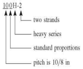
This convention makes the pitch directly readable from the chain number. In Ex. 17-5 ascertain the pitch from the selected chain number and confirm from Table 17-19.
EXAMPLE 17-5 Select drive components for a 2:1 reduction, 90-hp input at 300 rev/min, moderate shock, an abnormally long 18-hour day, poor lubrication, cold temperatures, dirty surroundings, short drive C/p = 25.
Expert Solution & Answer
Want to see the full answer?
Check out a sample textbook solution
Students have asked these similar questions
A 1000 RPM speed reducer and 12KW power drives a conveyor belt at 400 RPM. the distance between the centers is approximately 800mm.
Select a suitable chain for transmission, as follows:1) Solicitation with moderate shock, abnormal operating conditions, operating 24 hours a day.
There are two pairs of closed soft tooth surface spur gears A and B Parameters of A: modulus m = 2mm, number of teeth Z, = 40,Z, = 90, width of teeth b =60mm. %3D Parameters of B: modulus m = 4mm, number of teeth Z, = 20,Z, = 45, width of teeth b = 60mm. %3D The accuracy of the two pairs of gears is grade 8, and other conditions are the same. Try to compare the contact fatigue strength and bending fatigue strength of the two pairs of gears? And explain the reason?
Q2) A flat belt drive system is to be)
designed for an application in which
the input shaft speed is 1725 rpm, the
driven shaft speed is to be
approximately 960 rpm, and the power
to be transmitted has been estimated
as 2.5kW. The driven machine has been
evaluated and found to have
characteristics of moderate shock
loading during operation. The desired
center distance between driving and
driven pulleys is approximately 0.5m.
The recommended pulley diameter is
110mm. The belt is made of polyamid
with density of 0.95g/cc and the
coefficient of friction is 0.8. The
limiting design-allowable tension per
unit width for the polyamide is
613ON/m.a. If 5mm-thick belt material
were chosen for this application, what
belt width would be required?b. What
initial tension would be required for
?proper operation
Chapter 17 Solutions
Shigley's Mechanical Engineering Design (McGraw-Hill Series in Mechanical Engineering)
Ch. 17 - Example 17-2 resulted in selection of a 10-in-wide...Ch. 17 - A 6-in-widc polyamide F-l flat belt is used to...Ch. 17 - Prob. 3PCh. 17 - A flat-belt drive is to consist of two...Ch. 17 - In solving problems and examining examples, you...Ch. 17 - Return to Ex. 17-1 and complete the following. (a)...Ch. 17 - Prob. 7PCh. 17 - Prob. 8PCh. 17 - Prob. 9PCh. 17 - Two shafts 20 ft apart, with axes in the same...
Ch. 17 - Prob. 11PCh. 17 - Prob. 12PCh. 17 - A designer has to select a metal-belt drive to...Ch. 17 - Prob. 14PCh. 17 - Prob. 15PCh. 17 - Prob. 16PCh. 17 - Prob. 17PCh. 17 - Two B85 V belts are used in a drive composed of a...Ch. 17 - Prob. 19PCh. 17 - Prob. 20PCh. 17 - The geometric implications of a V-flat drive are...Ch. 17 - A 2-hp electric motor running at 1720 rev/min is...Ch. 17 - The standard roller-chain number indicates the...Ch. 17 - Prob. 24PCh. 17 - A double-strand no. 60 roller chain is used to...Ch. 17 - A four-strand no. 40 roller chain transmits power...Ch. 17 - Prob. 27PCh. 17 - Prob. 28PCh. 17 - Prob. 29PCh. 17 - Prob. 30PCh. 17 - Prob. 31PCh. 17 - Prob. 32PCh. 17 - Prob. 33PCh. 17 - For Prob. 17-29 estimate the elongation of the...
Knowledge Booster


Learn more about
Need a deep-dive on the concept behind this application? Look no further. Learn more about this topic, mechanical-engineering and related others by exploring similar questions and additional content below.Similar questions
- Design a chain drive to run a blower at 700 rpm for design factor of 1.5 moderate shock. The power to the blower is available from an 8 kW motor at 1400 rpm. The center distance is to be kept at 800 mm. Note the design should include the number of teeth of driven and driver sprocket, chain No, number of strands, and the length of the chain in term of chain pitch.arrow_forward480 ft-lbf First Gear (2.66) Final Drive (3.42) Figure 2 - Corvette Z06 and its transmission schematic. You start by measuring the 60-0 mph braking performance, which is accomplished along 30.56 m. The test weight (including the driver) was found to be 1510.5 kgf. Peak torque (@4800 rpm) 1st gear reduction Axle Torque Thrust Force After the braking test, you are asked to determine the maximum acceleration in the first gear. Consulting the manufacturer, you find out the following technical data: Final drive (differential) reduction Rolling radius of the rear tyres % weight on the rear tyres Table 1 - Technical data for the Corvette Z06 480 lbf-ft 2.66 3.42 0.327 m 65% 1) Assuming the maximum traction capacity of the tyres has been determined in the braking test, CALCULATE the maximum traction generated by the rear tyres in first gear. CALCULATE the available thrust force (i.e. traction) from the torque on the wheels.arrow_forwardCompute the contact stress number for the gear fain pair driven directly by an electrical motor. The driven machthe is concrete mixture with moderate shock, the other data are given below. Ks= 1.00, Km 1.21, Vt =1527 St/min, Av-11 Pd= 6, np= 1750rp.m, Np 20, No= 70, F=2.00/n Tp = 900ib, Dp= 3:333 in The material used for pioin an gear is Steelarrow_forward
- Q. No 4. rev/min, moderate shock, an abnormally long 18-hour day, poor lubrication, cold temperatures, dirty surroundings, short drive C/p = 25. Ks = 1.3 & Design factor = 1.5 Select chain drive components for a 3:1 reduction, 70-hp input at 300arrow_forwardQuestion (2) The followings are the compression spring particulars in slip clutch unit. You are asked to:- Axial force Spring mean Diameter 25 mm Compression Spring Particulars Og of SAE 6150 O, of Cr-Mo-Ni Steel 1600 MPa 1400 MPa 8 FDK 1000 N Spring index Shear stress in spring wire 5 8 FD3N Y= Gdt No. of active turns, N Modulus of rigidity of spring material, G Spring deflection 10 8 x 10* MPa Wahl factor, K 1.3 1. Calculate the shear stress in spring wire. 2. Choose the suitable spring material. . 3. Calculate the spring stiffness. 4. Determine the spring length in the system in working condition if the spring free length is 100 mm. 5. Recalculate the shear stress in spring wire if the axial force increases to 2000 N without changing the spring material (obtained in no. 2). Comment on your results.arrow_forwardThere are two pairs of closed soft tooth surface spur gears A and B,Parameters of A: modulus m = 2mm, number of teeth Z1 = 40, Z2 = 90 , width of teeth b = 60mm.Parameters of B : modulus m = 4mm, number of teeth Z1 = 20, Z2 = 45 , width of teeth b = 60mm.The accuracy of the two pairs of gears is grade8, and other conditions are the same. Try to compare the contact fatigue strength and bending fatigue strength of the two pairs of gears? And explain the reason.arrow_forward
- An engine of 175 mm bore and 375 mm stroke is governed by hit and miss type governor to 220 rpm. With a fixed setting of the gas supply and ignition advance, indicator diagrams gave the following values of mean effective pressure. Firing, positive loop 5.7 bar, negative loop 0.25 bar; missing negative loop 0.42 bar. When developing 6 kW the explosions were 100 per minute and the gas used was 0.1 m per minute. Calculate the friction power and assuming uniform gas supply per explosion, find the gas consumption per minute at no load.arrow_forward480 ft-lbf First Gear (2.66) Final Drive (3.42) Axle Torque Thrust Force Figure 2 - Corvette Z06 and its transmission schematic. You start by measuring the 60-0 mph braking performance, which is accomplished along 30.56 m. The test weight (including the driver) was found to be 1510.5 kgf. 1) "Fuel is spent to make the vehicle go uphill, as you are aware. However, the fuel will not be restored if the vehicle is brought back from the hilltop to the initial elevation level."ANALYSE this statement under the laws of Thermodynamics.arrow_forward. A square shaft of annealed AISI C1137 transmits a torsional moment of 1200 in-lb.What should be its size for medium shock?arrow_forward
- 1. A 10 hp. 1400 rpm motor uses a roller chain to drive a line-shaft at 400 rpm with a center to center distance of 2 ft. The motor shaft has a diameter of 1 % inches and the load applied is moderate shock. Determine the approximate length of the chain.arrow_forwardb) Design a self-aligning ball bearing with basic dynamic load rating of 69.5 KN to be used in the automobile industry to carry a thrust load of 1184 N. The expected life of the bearing is 5201 hours at 628 rpm. Take k=3 for all types of ball bearings. Take the value of the shock load factor as 1.7 and radial and axial load factors are 1.4 and 2.2 respectively, the rotational factor is 1. Calculate: i) Expected life of bearings in millions of revolutions ii) Design equivalent dynamic load in N iii) Basic equivalent dynamic load in N iv) Radial load acting on the bearing in Narrow_forwardThe length of stroke of a four cylinder four stroke cycle SI engine is1.6 times the diameter of the cylinder. The engine develops 25 kWbrake power at 2450 rpm. Each piston observes a mean effectivepressure of 8.5 bar and the mechanical efficiency is 86%. Find thediameter and stroke length of each cylinder.arrow_forward
arrow_back_ios
SEE MORE QUESTIONS
arrow_forward_ios
Recommended textbooks for you
 Elements Of ElectromagneticsMechanical EngineeringISBN:9780190698614Author:Sadiku, Matthew N. O.Publisher:Oxford University Press
 Mechanics of Materials (10th Edition)Mechanical EngineeringISBN:9780134319650Author:Russell C. HibbelerPublisher:PEARSON
 Thermodynamics: An Engineering ApproachMechanical EngineeringISBN:9781259822674Author:Yunus A. Cengel Dr., Michael A. BolesPublisher:McGraw-Hill Education
 Control Systems EngineeringMechanical EngineeringISBN:9781118170519Author:Norman S. NisePublisher:WILEY
 Mechanics of Materials (MindTap Course List)Mechanical EngineeringISBN:9781337093347Author:Barry J. Goodno, James M. GerePublisher:Cengage Learning
 Engineering Mechanics: StaticsMechanical EngineeringISBN:9781118807330Author:James L. Meriam, L. G. Kraige, J. N. BoltonPublisher:WILEY
Elements Of Electromagnetics
Mechanical Engineering
ISBN:9780190698614
Author:Sadiku, Matthew N. O.
Publisher:Oxford University Press
Mechanics of Materials (10th Edition)
Mechanical Engineering
ISBN:9780134319650
Author:Russell C. Hibbeler
Publisher:PEARSON
Thermodynamics: An Engineering Approach
Mechanical Engineering
ISBN:9781259822674
Author:Yunus A. Cengel Dr., Michael A. Boles
Publisher:McGraw-Hill Education
Control Systems Engineering
Mechanical Engineering
ISBN:9781118170519
Author:Norman S. Nise
Publisher:WILEY
Mechanics of Materials (MindTap Course List)
Mechanical Engineering
ISBN:9781337093347
Author:Barry J. Goodno, James M. Gere
Publisher:Cengage Learning
Engineering Mechanics: Statics
Mechanical Engineering
ISBN:9781118807330
Author:James L. Meriam, L. G. Kraige, J. N. Bolton
Publisher:WILEY
Power Transmission; Author: Terry Brown Mechanical Engineering;https://www.youtube.com/watch?v=YVm4LNVp1vA;License: Standard Youtube License