
Concept explainers
Videos
Refer to Figure P2.49 and assume
a. The mesh currents
b. The current through each resistor.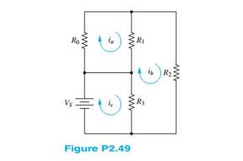
Want to see the full answer?
Check out a sample textbook solution
Chapter 2 Solutions
Principles and Applications of Electrical Engineering


- The figure below shows three resistors (R- 13.5 0, R -7.95 0, and Ry- 12.5 0) and two batteries connected in a circuit. 40.0 V R 22.0 V R3 (a) What is the current in each of the resistors? A I2 = A A (b) How much power is delivered to each of the resistors? P1- P2- P3-arrow_forwardGiven four resistors R1 = 100 ohms, R2=250 ohms, R3 = 350 ohms, and R4 = 200 ohms such that R1 and R2 in parallel will be connected in series with R3 and R4 in parallel. The series-parallel combination is connected across a 24-volt DC power supply. Find the voltage across R2 and voltage across R4 voltage drops across R2 and R4 are both 12 V voltage drop across R2 is 18.63 V and voltage across R4 is 5.37 V voltage drop across R2 is 8.63 V and voltage across R4 is 15.37 V voltage drop across R2 is 8.63 V and voltage across R4 is 15.37 Varrow_forward4.-For-labeled currents, draw an arrow to show the direction of the actual positive current. For labeled voltages, circle the node that is at the actual highest potential. Note that the positive and negative signs of the voltage represent the polarity of the probes of a voltmeter connected to the device. The value shown is the reading on the voltmeter. (segment of wire) 2A -2A -5A 2.de 3A TA Cov E 5V 12V + 3V -10V -201arrow_forward
- V = 36 V Refer to the figure at the right. iz What is the potential of point a with respect to point b when switch S is open? 3 0 What is the current through switch S S When it is closed? What is the equivalent resistance of this combination of resistors when S is closed?arrow_forwardShown in the figure is an RL series circuit in which R= 10 ohms and L= 0.1 Henry. This is energized by a 24 volt DC source. If the switch is closed at t=o. Find the time when Power across R = Power across L.arrow_forward3. Given the circuit of figure a. Determine the values of all resistors. b. Calculate the currents through R1, R2, and R4 c. Find the currents Il and 12. d. Find the power dissipated by resistors R2, R3 and R4 P = 1.152 W 30 mA RI R2 50 mA R 12 mA ww 48 V R4arrow_forward
- Determine the current of the circuit below. Then apply Ohm's law to determine the expected voltage drops across R1, R2, and R3. Record these values. Include demonstration of Kirchhoff's Voltage Law. R1 1k 9Vdc R2 220 R3 10karrow_forwardUsing the circuit of below with R1 = 1 kQ, R2 = 220 Q, R3 = 10 kQ, and V = 9 volts, Determine the theoretical voltages across R1, R2 and R3. Apply Kirchhoff's Current Law and Ohm's Law to determine the expected currents Is. I1, l2 and I3. Record these values. R1 1k R3 10k 13 R2 9Vdc 220arrow_forwardUsing the rules for parallel circuits and Ohmslaw, solve for the missing values. ETE1E2E3E4ITl1I2l33.2AI4RT3.582R116R210R3R420PTP1P2P3P4arrow_forward
- Each of the cells shown in the figure has an emf of 1.50 V and a 0.0750-ohm internalresistance. Find I1, I2, and I3.arrow_forwardA 20-ohm resistor is connected in parallel with a variable resistor R. The parallel combination is then connected in series with a 4-ohm resistor and connected across a 240 V source. Determine the minimum value of Rif the power of R is equal to the power taken by the 4-ohm resistor.arrow_forward2. Three resistors R1, R2 and R3 are connected in series parallel with R1 in series with parallel combination of R2 and R3. The whole combination is connected across a 120V DC source. Resistors R1, R2 and R3 takes 750 w, 250 W and 200 W, respectively. Calculate the resistance R2. Why are street lights connected in parallel and not in series, explain.arrow_forward
 Delmar's Standard Textbook Of ElectricityElectrical EngineeringISBN:9781337900348Author:Stephen L. HermanPublisher:Cengage Learning