
Videos
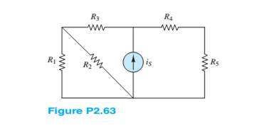
For the circuit shown in Figure P2.58, assume
a. The number of nodes in the circuit.
b. The power delivered by the source
c. The equivalent resistance seen by the source
Want to see the full answer?
Check out a sample textbook solution
Chapter 2 Solutions
Principles and Applications of Electrical Engineering


- a. Thévenin's and Norton's theorem are two examples of circuit theorem. With the help of equivalent circuits, distinguish the difference between them.arrow_forwardb) The circuit in Figure Q2(b) is referred. i. Show the supernode in the circuit. Explain the reason for your answer. ii. By using nodal analysis with supernode, solve for the node voltages at each assigned nodes in the circuit. 2 A 12 V Figure Q2(b)arrow_forwardRefer to the following circuit diagram. Find the current Is1 supplied by source E₁. and current Is2 supplied by E2. E₁ 130V Ist A Z₁ 3352 N Z₂ 1052 B D Z₁ 2402 Z 502 C Isz E₂ 110Varrow_forward
- An electric circuit with two DC power supplies is shown in Figure A (E1 and E2). Assume that E1 = 200 V, E2 = 120 V, and that all resistors have similar value of R = 20. Using the Superposition theory and the Current Divider Rule, simplify the circuit and determine the current (IR6) across resistor R6.arrow_forwardQ1: Use a qualitative analysis to identify the filter type for the circuit shown in Figure-1 below. Hence use a quantitative analysis to calculate its parameters. Vin L Vout Figure 1arrow_forward5. The following circuit is a schematic of an electrical circuit in a house. R₁, R₂, and R4 model the wiring's resistance, while R3, Rs, and R6 are modeling 75 W lightbulbs as a 2000 resistance (R = V2/P). The 120 V source represents the breaker panel of the house. Determine the following: a. The power of each bulb, taking into account the wire resistance. b. What do you notice about the bulb powers in this circuit? V1 120V R1 4.7 R3 200 R2 w 4.7 R5 200 R4 4.7 R6 200arrow_forward
- Design a circuit that will have an outcome of the highest equivalent resistance across the terminals with a 30Vdc source. Given that the R1 = 10 R2 = 50 R3 = 85. Determine the equivalent resistance from the combination of resistors, R123, R12, R23, and R1.arrow_forwardconsider the following circuit composed of three resistors and two batteries. each resistor has a resistance of 2.00 ohms. assume that the branch currents flow in the directions indicated in the figure. note that: I = 0.600 A I = 0.800 A E1= 10.0V R1= 10 ohms R3= 5 ohms Solve: a.) Write out the equation relating the currents by using the junction rule at node a. Additionally, what is the magnitude of I3? b.) What is the resistance of R2? c.) what is E2?arrow_forwardSince R1=3538.58ohm, R2=5870.13ohm and Ri-Infinite in the circuit given in the figure, write the equivalent resistance seen between AB terminals in Ohms. R1 Kuvvetlendirici R2 Ri B A.arrow_forward
- The circuit shown below is an example of a simple voltage regulator. Determine the current through R2 in mA. Assume the following values for the resistors: R1 = 13 kn, R2 = 10 kn. Express your answer using three decimal places. Assume the opamp is ideal and Q1's B is infinity. Q1 VCC Vref NPN U1 OUT 20V 1.2V R1 R2 + +arrow_forwardResistors are said to be connected in parallel Select one: a. Circuit elements connected in parallel have the same voltage across their terminals Eion b. All of the answers C. When two circuit elements connect at a single node pair Previous page Next p Jump to... Return to: Generalarrow_forwardVi Ri Vo Il The elements in the circuit shown have the following values: R = 2570.11 N. R2 = 4277.34 N. R3 = 4236.39 N. R4 = 622.17 N. Vị = 102.816373 V. h = 0.0176 A. Determine the following: a.) Using any circuit method you prefer, solve for the voltage V, b.) Determine the current flowing through R4. c.) Determine the magnitude of the current flowing through the resistor R3 (Hint: Assume the current flows up through R3). d.) Determine the power dissipated by R4 (in Watts).arrow_forward
 Introductory Circuit Analysis (13th Edition)Electrical EngineeringISBN:9780133923605Author:Robert L. BoylestadPublisher:PEARSON
 Delmar's Standard Textbook Of ElectricityElectrical EngineeringISBN:9781337900348Author:Stephen L. HermanPublisher:Cengage Learning
 Programmable Logic ControllersElectrical EngineeringISBN:9780073373843Author:Frank D. PetruzellaPublisher:McGraw-Hill Education
 Fundamentals of Electric CircuitsElectrical EngineeringISBN:9780078028229Author:Charles K Alexander, Matthew SadikuPublisher:McGraw-Hill Education
 Electric Circuits. (11th Edition)Electrical EngineeringISBN:9780134746968Author:James W. Nilsson, Susan RiedelPublisher:PEARSON
 Engineering ElectromagneticsElectrical EngineeringISBN:9780078028151Author:Hayt, William H. (william Hart), Jr, BUCK, John A.Publisher:Mcgraw-hill Education,