WATER RESOURCES ENGINEERING
3rd Edition
ISBN: 9781119490579
Author: Mays
Publisher: WILEY
expand_more
expand_more
format_list_bulleted
Concept explainers
Videos
Textbook Question
Chapter 4, Problem 4.5.2P
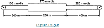
The rate of flow in the pipe system in Figure is
Expert Solution & Answer
Want to see the full answer?
Check out a sample textbook solution
Students have asked these similar questions
The diameter of a pipe changes gradually from 6 inches at A to 18
inches at B. A is 15 ft lower than B. If the pressure at A is 10 lbs per
square inch and at B, 7 lbs per square inch when there are 5.0 cubic ft
per second flowing, determine:
a. the direction of flow.
b. the frictional loss between the two points
B. If in Problem 1 the direction of flow is reversed, determine the
pressure at A if all other factors, including the frictional loss, remain the
same.
C. In Problem 1, determine the diameter of pipe at B in order that the
pressure at that point will also be 10 lbs per square inch, all other
factors remaining constant.
D. Determine the discharge in Problem 1, assuming no frictional loss, all
other conditions remaining as stated.
E. What would be the difference in pressure in pounds per square inch
between A and B, Problem 1, if there were 6.2 cubic ft per second
flowing, neglecting friction.
What is pipe roughness? A pump is located 5 m above the surface
= 8170 M/m¹) in a closed tank. The pressure in the space above liquid surface is
35 Kpa. The suction line to the pump is 15 m of 15 cm diameter pipe (/=
0.025). The discharge from the pump is 60 m of 20 cm diameter pipe (/= 0.03).
The pipe discharges in a submerged fashion to an open tank whose free liquid
surface is 3 m lower than the liquid surface in the pressure tank. If pump puts
1.5 kW Into the liquid, determine the flow rate and the pressure in the pipe on
the suction side of the pump. Assume turbulent flow.
Q2) What is the pressure at point (B)inside the pipe shown in figure
below if the water jet velocity at point (A) is 18 m/s..
15m
D= 75 mm
D 200 mm
0.5 m
B-
Knowledge Booster


Learn more about
Need a deep-dive on the concept behind this application? Look no further. Learn more about this topic, civil-engineering and related others by exploring similar questions and additional content below.Similar questions
- The pressure gauges are inserted at A and B in a vertical pipe converging water. The diameters at A and B are 150mm and 75mm respectively. The point B is 2.3m below point A. When rate of flow down the pipe is 0.021m³/s. The pressure at B is 117.72 KN/m² greater than at A. The losses in pipe between A and B are expressed as(KVa²/2g) where Va is velocity of A. Find the value of K. If the pressure gauges at A and B are replaced by tubes filled with water and connectef to a u-tube containing Hg(SHg=13.6) calculate the value of the reading manometer.arrow_forwardThe diameter of a pipe carrying oil (s=0.92) changes gradually from 400 mm at A to 600 mm at B. Point A is 3.6 m lower than B. If the pressure at A is 70 KPa and that at B is 49 KPa when 140 L/s is flowing, determine the direction of flow; (b) the frictional loss between the two points.arrow_forwardIn the figure, friction loss between A and B is neglected while between B and C it is 0.2 (VB²/2g). Find the gauge pressure at C (in kPa) if the water is flowing from A to C at a rate of 304 L/s. Pipes A and C are 443 mm in diameter and Pipe B is 131 mm in diameter. The gauge pressure at A B B is 7.9 kPa.arrow_forward
- Determine the pressure at the center of the pipe from the piezometer shown. 200mm WATER 75mmØPIPEarrow_forwardThe pressure at point 2 shown in Figure is not to fall below 4.14 Bar when the flowrate from the tank is 0.028 m^3/ sec. Determine the minimum height, h, of the water tank under the assumption that (a) minor losses are negligible, (b) minor losses are not negligible. 3 m Figure No.3 Kentrance = 0.5 h The pipe is plastic of 15 cm diameter and (e/D=D0) 1.8 m (2) Main line 450 m with 15 elbows of 90 degreearrow_forward1 a) A 2-mm-diameter clean glass tube is inserted in water at 15°C (Figure 1.2). Determine the height that the water will climb up the tube. The water makes a contact angle of 0° with the clean glass. ADo h W=y¥ Air Water Figure 1.2arrow_forward
- 4.5.4. If the pressure difference between points 1 and 2 in Figure P4.5.4 is 25 psi. What will be the flowrate? The pipes are galvanized iron with k, = 0.0005 ft. Take v = 1.06 x 10* ft/s and neglect minor losses. 2000 ft, 8 in dia 10 in dia 2. B 1600 ft, 6 in dia e 800 ft, 10 in dia- Figure P4.5.4arrow_forwardA copper tube 80 mm diameter and 2.5 mm thick is plugged at its ends and filled with water without applying any external pressure . It is observed that when an axial push is applied at ends , the water pressure rises to 0.12 N / mm² . Find value of axial push . Take Ecu = 102 GPa , Kwater = 2.2 GPa and μ = 0.32 .arrow_forwardThe gauge pressure of water at A is 150.5 kPa. Water flows through the pipe at A with a velocity of 18 m/s, and out the pipe at B and C with the same velocity v. Neglect the weight of water within the pipe and the weight of the pipe. The pipe has a diameter of 50 mm at A, and at B and C the diameter is 31 mm. pw = 1000 kg/m³. (Figure 1) Figure v B v y L. 18 m/s 1 of 1 Part A Determine the x component of force exerted on the elbow necessary to hold the pipe assembly in equilibrium. Express your answer to three significant figures and include the appropriate units. F = 11176 Submit μА Part B Previous Answers Request Answer X Incorrect; Try Again; 4 attempts remaining N Determine the y component of force exerted on the elbow necessary to hold the pipe assembly in equilibrium. Express your answer to three significant figures and include the appropriate units. μA Fy=11115 Provide Feedback ? N Submit Previous Answers Request Answer ? X Incorrect; Try Again; 5 attempts remainingarrow_forward
- The gauge pressure of water at A is 150.5 kPa. Water flows through the pipe at A with a velocity of 18 m/s, and out the pipe at B and C with the same velocity v. Neglect the weight of water within the pipe and the weight of the pipe. The pipe has a diameter of 50 mm at A, and at B and C the diameter is 29 mm. pw = 1000 kg/m³. (Figure 1) Figure v B v y -X A 1 18 m/s 1 of 1 Part A Determine the x component of force exerted on the elbow necessary to hold the pipe assembly in equilibrium. Express your answer to three significant figures and include the appropriate units. F₁ = Submit Part B F₁ = μA Submit Value Request Answer Determine the y component of force exerted on the elbow necessary to hold the pipe assembly in equilibrium. Express your answer to three significant figures and include the appropriate units. μA Value Units Request Answer ? Units ?arrow_forwardConsider that we have a horizentral pipe, like shown in the sketh, which is carrying in this case, cooling water at 10 ℃。The elevation of the big tank of cooling water is 100 m, the elevation of the center line of the pipe is 20 m, the length of the pipe is 2000 m. Head loss in the pipe is , D=20 cm, the rate of flow is 0.06 m3/s, . Please calculate the pressure in the pipe.arrow_forwarda)Determine the difference in pressure between A and B in kPa if h = 0.15 and SG of oil is 0.862.B)Determine the pressure in the pipe in psi.arrow_forward
arrow_back_ios
SEE MORE QUESTIONS
arrow_forward_ios
Recommended textbooks for you

 Structural Analysis (10th Edition)Civil EngineeringISBN:9780134610672Author:Russell C. HibbelerPublisher:PEARSON
 Principles of Foundation Engineering (MindTap Cou...Civil EngineeringISBN:9781337705028Author:Braja M. Das, Nagaratnam SivakuganPublisher:Cengage Learning
 Fundamentals of Structural AnalysisCivil EngineeringISBN:9780073398006Author:Kenneth M. Leet Emeritus, Chia-Ming Uang, Joel LanningPublisher:McGraw-Hill Education
 Traffic and Highway EngineeringCivil EngineeringISBN:9781305156241Author:Garber, Nicholas J.Publisher:Cengage Learning
Structural Analysis (10th Edition)
Civil Engineering
ISBN:9780134610672
Author:Russell C. Hibbeler
Publisher:PEARSON
Principles of Foundation Engineering (MindTap Cou...
Civil Engineering
ISBN:9781337705028
Author:Braja M. Das, Nagaratnam Sivakugan
Publisher:Cengage Learning
Fundamentals of Structural Analysis
Civil Engineering
ISBN:9780073398006
Author:Kenneth M. Leet Emeritus, Chia-Ming Uang, Joel Lanning
Publisher:McGraw-Hill Education
Traffic and Highway Engineering
Civil Engineering
ISBN:9781305156241
Author:Garber, Nicholas J.
Publisher:Cengage Learning
Understanding Stresses in Beams; Author: The Efficient Engineer;https://www.youtube.com/watch?v=f08Y39UiC-o;License: Standard Youtube License