
Concept explainers
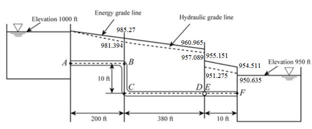
The drawing of the hydraulic gradient line and the energy grade line of the given system.
Explanation of Solution
Given:
Formula used:
Calculation:
The given figure is shown below:
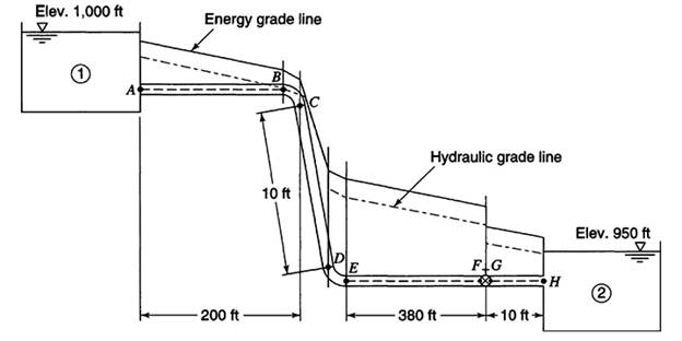
The flow between reservoir 1 and reservoir 2 is given by
The head loss is given by
The total minor head loss is given by
The relative roughness of pipe is given by
The value of the friction factor is 0.0165 from Moody’s diagram.
Now, substituting the value of the friction factor in the equation (1)
The discharge is given by
The velocity head is given by
The total head loss in the flow from A to B is given by
The hydraulic gradient line at B is given by
The energy gradient line at B is given by
Keep the hydraulic gradient line at point C the same as the hydraulic gradient line at point B.
The hydraulic gradient line at point C is given by
The energy gradient line at C is given by
The hydraulic gradient line at D is given by
The energy gradient line at D is given by
The hydraulic gradient line at E is given by
The energy gradient line at E is given by
The hydraulic gradient line at F is given by
The energy gradient line at F is given by
Want to see more full solutions like this?


- The pressure drop between node 1 and 2 in the following figure is 3 psi. The pipes are smooth. What is the total flow rate? Note: 1 psi = 144 psf and 1 inch = 1/12 ft. D = 3 in L = 250 ft D = 2 in L= 200 ft 2.arrow_forward4. Piezometric tubes are tapped into a pipe section as shown in the figure below. The liquid is incompressible and flowing at a volumetric flowrate of 0.35 m³ s-¹. The piezometric head is 1 m at the upstream location (1) and 0.5 m at the throat (2). The pipe diameter at the upstream location (1) is 0.5 m. Answer the following: 1 m Flow Streamline- 0.5 m Datum Hint: the piezometric head is the sum of the elevation and pressure heads. (a) Find the velocity in the upstream section. (b) Find the velocity in the throat section. (c) Find the diameter in the throat section. (d) Based on your findings in (a) and (b), qualitatively describe how pressure and velocity are related along the streamline.arrow_forwardQ1) Given is a three-pipe series system, as in Fig. 150,000 Pa, and the elevation drop is ZA - ZB = 5 m. The pipe data are The total pressure drop is pa - PB = Pipe L, m d, cm €, mm eld 1 100 8 0.24 0.003 2 150 6. 0.12 0.002 3 80 4 0.20 0.005 The fluid is water, p 1000 kg/m and v = 1.02 x 10⁻⁶ m/s. Calculate the flow rate Q in m/h through the system. (3 (2 A Barrow_forward
- (Multiple pipes) The three tanks shown in the figure below are connected by pipes with friction factors of 0.03 for each pipe. Determine the water velocity in each pipe. Neglect minor losses. Elevation = 857 ft Elevation = 822 ft D = 1.1 ft D = 1.0 ft l = 700 ft l = 800 ft (1) (A) V₁ = i (B) V₂ = i (C) V3 = i (3) D = 1.2 ft € = 600 ft (2) ft/s ft/s ft/s Elevation = 793 ftarrow_forwardFigure Q1 shows an internal piping system of a building. The pipe is uPVC of total length 35 m. The minor loss coefficients are as shown in the figure. The flow velocity in the pipe is designed to be 1.0 m/s and the residual pressure head at appliance X must be at least 0.8m. Determine the required pipe diameter using Darcy Weisbach formula. Level 8.5 m k = 0.8 Water tank IT Roof beam Minor loss coefficients: E Stop valve, k = 10 O 90°elbow, k = 1 Level 4 m Figure Q1arrow_forwardPart 2Two pipes are connected by a manometer as shown. Determine the pressure difference, between the pipes in kPa.arrow_forward
- Situation XX: In the figure shown, z, = 4 m, length of pipe from the reservoir to the pump is 120 %3D m, from the pump to the nozzle is 1000 m. The diameters of pipes are 0.60 and 0.45 m respectively. The gage pressure at B (the suction side of the pump) is -64 KPa. Neglect minor losses. В C P. 0.45 m diam. LCD = 1000 m %3D Zp = 4 m f = 0.02 0.60 m diam. LAB = 120 m f = 0.02 %3D 52. Compute the velocity of water in pipe AB. a. 2.297 m/s b. 1.452 m/s c. 3.147 m/s d. 2.672 m/s 53. Compute the velocity of water in pipe CD. a. 1.23 m/s b. 4.08 m/s c. 3.56 m/s d. 5.59 m/s 54. Compute the discharge of the pipe from A to B due to pumping. a. 0.65 m3/s b. 0.45 m3/s c. 0.89 m³/s d. 0.25 m3/s 60 m, f= 0.02 m and loss of head itharrow_forwardWater flows from reservoir A to B through the three concrete pipes shown below. Assume that concrete has f=0.023. Neglect all minor losses. 2500 m 400 mm Ø 20 m and Dnew 1850 m 300 mm Ø 800 m 200 mm g a) Determine the flow rate from A to B in m³/s b) Determine the diameter (mm) of an equivalent pipe made out of steel with f=0.012.arrow_forward2. A tank and piping system are shown below. The total length of PVC pipe is 2500 ft and discharges water into the atmosphere. The pipeline has an open globe valve and four threaded elbows; h1 = 10 ft and h2 = 45 ft." a. If the discharge is 0.5 cfs, what NPS should be used for the PVC pipe (ks = 0.00006 inch). b. What is the pressure at A, the midpoint of the pipeline? c. Draw the EGL and HGL. h2 Water T = 10°C (50°F) Globe valvearrow_forward
- Orifice meter with orifis cross-section 0.00785 m2 is inserted in a pipe of cross-section 0.0314 m2. The pressure gauge fitted upstream and downstream of orifice give reading of 19.62 N/cm2 and 9.81 N/cm2 respectively. Determine the value of dischareg using Cd=0.6.arrow_forwardQ1 Given is a three-pipe series system, as in Fig. The total pressure drop is py — ps = 150,000 Pa, and the elevation drop is z4 — 25 = 5 m. The pipe data are Pipe L.om d, em e mm eld 1 100 8 024 0.003 2 150 6 0.12 0.002 3 80 4 0.20 0.005 The fluid is water, p = 1000 kg/m’ and v = 1.02 X 10~° m%s. Calculate the flow rate Q in mh through the system. o © 0O Al — —_— — B T Uarrow_forwardabsolute roughness is o.03mm (for both sections), Determine the height H. Neglect local losses. Tip: Losses in pipes connected one after another (as in the figure) they add up 2. Consider the system shown. If the flow is Q = 220 lts / s and the H L=500 m D=45 cm L=800 m D=30 cmarrow_forward

 Structural Analysis (10th Edition)Civil EngineeringISBN:9780134610672Author:Russell C. HibbelerPublisher:PEARSON
 Principles of Foundation Engineering (MindTap Cou...Civil EngineeringISBN:9781337705028Author:Braja M. Das, Nagaratnam SivakuganPublisher:Cengage Learning
 Fundamentals of Structural AnalysisCivil EngineeringISBN:9780073398006Author:Kenneth M. Leet Emeritus, Chia-Ming Uang, Joel LanningPublisher:McGraw-Hill Education
 Traffic and Highway EngineeringCivil EngineeringISBN:9781305156241Author:Garber, Nicholas J.Publisher:Cengage Learning