
Loose Leaf for Engineering Circuit Analysis Format: Loose-leaf
9th Edition
ISBN: 9781259989452
Author: Hayt
Publisher: Mcgraw Hill Publishers
expand_more
expand_more
format_list_bulleted
Concept explainers
Videos
Textbook Question
Chapter 6, Problem 42E
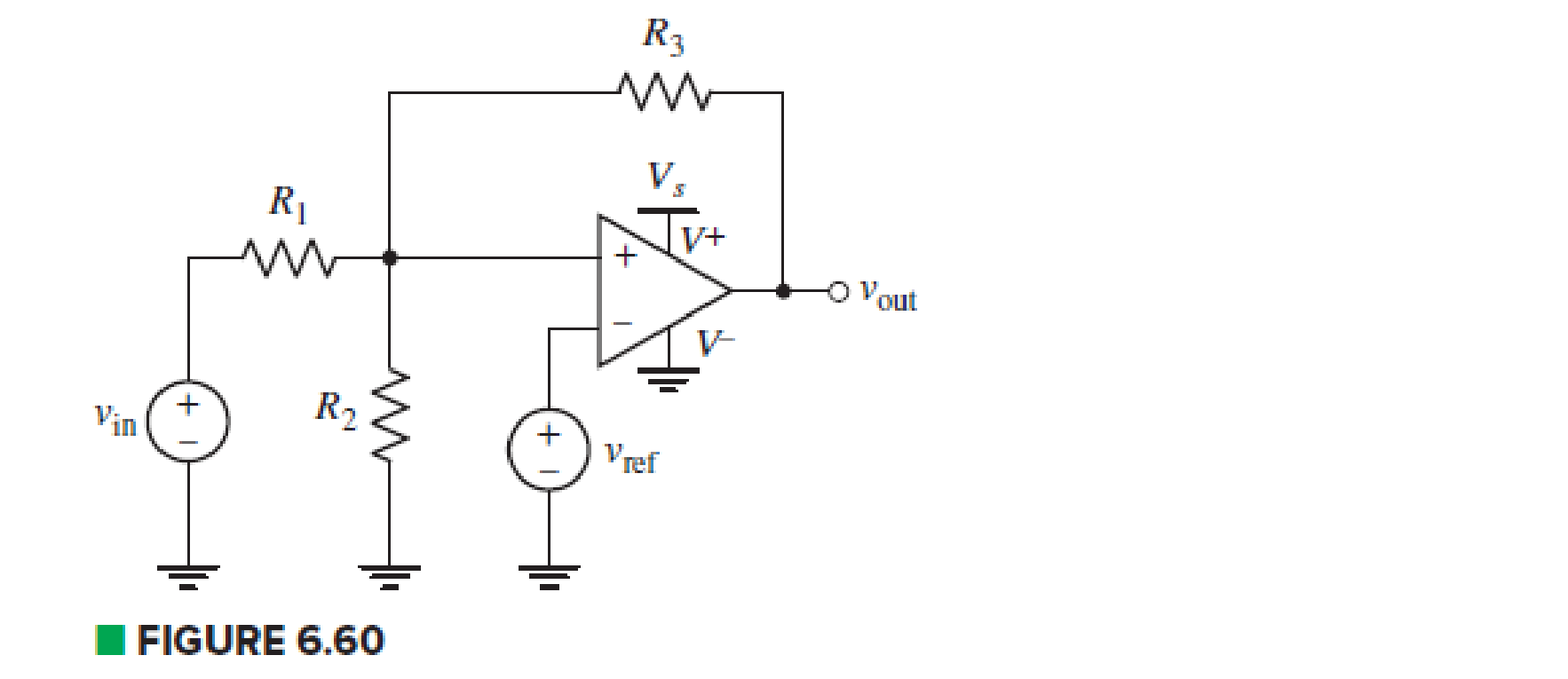
Examine the comparator Schmitt trigger circuit in Fig. 6.60. containing an input voltage vin, reference voltage vref, and single power supply Vs. Determine the trigger voltages in terms of circuit parameters, and sketch the output characteristics vout, versus vin.
Expert Solution & Answer
Want to see the full answer?
Check out a sample textbook solution
Students have asked these similar questions
signal system subject
use intergration and prove it with graph
Q6.) Identify whether the following statement are true(T) or false (F)
4- A piezo-electrical transducer is an example for active transducer.
5- The (1) is remove form control register in successive approximation DVM when
(Vin) is greater than VD (A/D convertor voltage).
Questiona. In an experiment the voltage required for the device is 9V dc but unfortunately the transformer available is of 220-6 Vdc. Design a circuit which can power the device (use only methods that we have studied excluding Zener diode)b. Explain the behavior of the following circuits if the input signal is triangular wave of peak voltage 5V and the biasing battery of 3V
Chapter 6 Solutions
Loose Leaf for Engineering Circuit Analysis Format: Loose-leaf
Ch. 6.2 - Derive an expression for vout in terms of vin for...Ch. 6.2 - Prob. 2PCh. 6.3 - An historic bridge is showing signs of...Ch. 6.4 - Design a circuit that provides a 12 V output if a...Ch. 6.4 - Design a noninverting Schmitt trigger that that...Ch. 6.5 - Assuming a finite open-loop gain (A), a finite...Ch. 6.5 - Use SPICE to simulate a voltage follower using an...Ch. 6 - For the op amp circuit shown in Fig. 6.39,...Ch. 6 - FIGURE 6.39 Determine the power dissipated by a...Ch. 6 - For the circuit of Fig. 6.40, calculate vout if...
Ch. 6 - For the circuit in Fig. 6.40, find the values of...Ch. 6 - (a) Design a circuit which converts a voltage...Ch. 6 - Prob. 6ECh. 6 - For the circuit of Fig. 6.40, R1 = RL = 50 ....Ch. 6 - Prob. 8ECh. 6 - (a) Design a circuit using only a single op amp...Ch. 6 - Prob. 11ECh. 6 - Determine the output voltage v0 and the current...Ch. 6 - Prob. 13ECh. 6 - Prob. 14ECh. 6 - Prob. 15ECh. 6 - Prob. 16ECh. 6 - Consider the amplifier circuit shown in Fig. 6.46....Ch. 6 - Prob. 18ECh. 6 - Prob. 19ECh. 6 - Prob. 20ECh. 6 - Referring to Fig. 6.49, sketch vout as a function...Ch. 6 - Repeat Exercise 21 using a parameter sweep in...Ch. 6 - Obtain an expression for vout as labeled in the...Ch. 6 - Prob. 24ECh. 6 - Prob. 25ECh. 6 - Prob. 26ECh. 6 - Prob. 27ECh. 6 - Prob. 28ECh. 6 - Prob. 29ECh. 6 - Prob. 30ECh. 6 - Prob. 31ECh. 6 - Determine the value of Vout for the circuit in...Ch. 6 - Calculate V0 for the circuit in Fig. 6.55. FIGURE...Ch. 6 - Prob. 34ECh. 6 - The temperature alarm circuit in Fig. 6.56...Ch. 6 - Prob. 36ECh. 6 - For the circuit depicted in Fig. 6.57, sketch the...Ch. 6 - For the circuit depicted in Fig. 6.58, (a) sketch...Ch. 6 - For the circuit depicted in Fig. 6.59, sketch the...Ch. 6 - In digital logic applications, a +5 V signal...Ch. 6 - Using the temperature sensor in the circuit in...Ch. 6 - Examine the comparator Schmitt trigger circuit in...Ch. 6 - Design the circuit values for the single supply...Ch. 6 - For the instrumentation amplifier shown in Fig....Ch. 6 - A common application for instrumentation...Ch. 6 - (a) Employ the parameters listed in Table 6.3 for...Ch. 6 - Prob. 49ECh. 6 - For the circuit of Fig. 6.62, calculate the...Ch. 6 - Prob. 51ECh. 6 - FIGURE 6.63 (a) For the circuit of Fig. 6.63, if...Ch. 6 - The difference amplifier circuit in Fig. 6.32 has...Ch. 6 - Prob. 55ECh. 6 - Prob. 56ECh. 6 - Prob. 57ECh. 6 - Prob. 58ECh. 6 - Prob. 59ECh. 6 - Prob. 60ECh. 6 - A fountain outside a certain office building is...Ch. 6 - For the circuit of Fig. 6.44, let all resistor...
Knowledge Booster


Learn more about
Need a deep-dive on the concept behind this application? Look no further. Learn more about this topic, electrical-engineering and related others by exploring similar questions and additional content below.Similar questions
- 6. Determine the approximate values of each of the following quantities in Figure 6. a. b. If C. Vout d. Closed loop gain 22k0 www 22 k Figure 6 Jinarrow_forwardb.com Snubbers are an essential part of power electronics to protect the active devices. Design a snubber circuit and explain how thyristors are protected against high di/dt and high dv/dt.arrow_forward4. Assume the following data from the Zener diode datasheet: Zener knee current =0.25mA, Zener Max Current=100mA, and max de power dissipation = 1 W, and regulated output voltage = 7.5 V. For the circuit below answer the following questions (a-b): V2 R1 www 1kQ Fig. 3 D2 R2 6 1.arrow_forward
- 1) For a series regulator show that the output voltage can be made to be dependent only on a reference voltage and the feedback ratio. 2) list the 5 planar processes for Ic fabrication and explain them. 3) A circuit is built around a bi-polar NPN transistor. The base network has a diode and a capacitor in series while the collector is connected to the power supply through a resistor. if the resistor is connected to ground; i) draw the circuit ii) provide all the masking layout of the circuit 4) Explain the significance of the buried layer in npn transistor fabrication. 5) Draw the lateral view of the layout of a lateral pnp transistor. Label all the diffusion regions. 6) state five differences between series regulators and switching regulators.arrow_forward3. (in clipping circuit) Drive an expression to find Vout (peak) in terms of Vin (peak) & FRarrow_forwardI need to design a multi stage amplifier with the following specs:arrow_forward
- Question No. 2 a Inan experiment the voltage required for the device is 9V dc but unfortunately the transformer avai lable is of 220-6 V dc. Design a circuit which can power the device (use only methods that we have studied excluding Zener diode) b. Explain the behavior of the foll owing circuits if the input signal is triangular wave of peak voltage 5V and the biasing battery of 3V 4-arrow_forwardc) When considering thyristor switching why is Isolated Gate Control needed ? d) The filtered rectifier output is now feeds the regulator circuit shown in figure Q6b. i) Name the type of regulator shown in the shaded area and briefly describe its operation. ii) If the voltage, VL, that appears across the potential divider is regulated to 5V what size zener diode is used? The entire circuit uses the op-amp comparator to iii) allow the limit on the maximum load current to be varied. Explain the operation of the circuit and identify the maximum load current, IL , allowed if the potentiometer's output is 4V and Rx is 20 ?arrow_forwardA) Design with drawing an Op-Amp series voltage regulator to give a regulated O/P voltage of 12V for an I/P of 15V B) Calculate the line regulation if the I/p increases to 4V leads to increase the O/P voltage to 0.02V.arrow_forward
- 3) Consider the Zener-diode voltage regulator shown below. Suppose you design this circuit to drive (supply) a load resistance RL. The supply voltages to the op-amp are +15 V and -15 V (not shown). a) What is Vout? b) If R = 1 k 2, what is the smallest R, that the circuit can handle without "sagging" the output voltage? c) What should be the power rating of the resistor R? Be explicit about your assumptions. +15 V R Vout IN4738 CS Scanned with CaScannerarrow_forwardEx) A standard two-junction thermocouple configuration is being used to measure the temperature in a wind tunnel. The reference junction is held at a constant temperature of 10 °C. We have only a thermocouple table referenced to 0 °C. Determine the output voltage when the measuring junction is exposed to an air temperature of 100 °C.arrow_forwardIt is connected to the input of a transistor (BJT) amplifier circuit with a gain of "-50" with a peak value of 100mV. a sine sign is applied a) Draw the circuit. b) Underline the input and output voltages by specifying their values.arrow_forward
arrow_back_ios
SEE MORE QUESTIONS
arrow_forward_ios
Recommended textbooks for you
 Introductory Circuit Analysis (13th Edition)Electrical EngineeringISBN:9780133923605Author:Robert L. BoylestadPublisher:PEARSON
 Delmar's Standard Textbook Of ElectricityElectrical EngineeringISBN:9781337900348Author:Stephen L. HermanPublisher:Cengage Learning
 Programmable Logic ControllersElectrical EngineeringISBN:9780073373843Author:Frank D. PetruzellaPublisher:McGraw-Hill Education
 Fundamentals of Electric CircuitsElectrical EngineeringISBN:9780078028229Author:Charles K Alexander, Matthew SadikuPublisher:McGraw-Hill Education
 Electric Circuits. (11th Edition)Electrical EngineeringISBN:9780134746968Author:James W. Nilsson, Susan RiedelPublisher:PEARSON
 Engineering ElectromagneticsElectrical EngineeringISBN:9780078028151Author:Hayt, William H. (william Hart), Jr, BUCK, John A.Publisher:Mcgraw-hill Education,
Introductory Circuit Analysis (13th Edition)
Electrical Engineering
ISBN:9780133923605
Author:Robert L. Boylestad
Publisher:PEARSON
Delmar's Standard Textbook Of Electricity
Electrical Engineering
ISBN:9781337900348
Author:Stephen L. Herman
Publisher:Cengage Learning
Programmable Logic Controllers
Electrical Engineering
ISBN:9780073373843
Author:Frank D. Petruzella
Publisher:McGraw-Hill Education
Fundamentals of Electric Circuits
Electrical Engineering
ISBN:9780078028229
Author:Charles K Alexander, Matthew Sadiku
Publisher:McGraw-Hill Education
Electric Circuits. (11th Edition)
Electrical Engineering
ISBN:9780134746968
Author:James W. Nilsson, Susan Riedel
Publisher:PEARSON
Engineering Electromagnetics
Electrical Engineering
ISBN:9780078028151
Author:Hayt, William H. (william Hart), Jr, BUCK, John A.
Publisher:Mcgraw-hill Education,
Differential Amplifiers Made Easy; Author: The AudioPhool;https://www.youtube.com/watch?v=Mcxpn2HMgtU;License: Standard Youtube License