
Concept explainers
Videos
A common application for instrumentation amplifiers is to measure voltages in resistive strain gauge circuits. These strain sensors work by exploiting the changes in resistance that result from geometric distortions, as in Eq. [6] of Chap. 2. They are often part of a bridge circuit, as shown in Fig. 6.61a, where the strain gauge is identified as RG. (a) Show that
AD622 Specifications
Amplifier gain G can be varied from 2 to 1000 by connecting a resistor Between pins 1 and 8 with a value calculated by
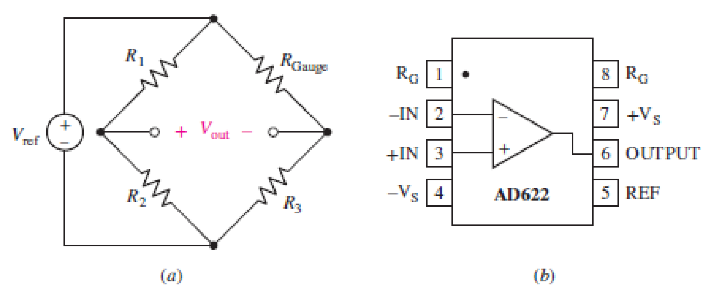
FIGURE 6.61
Want to see the full answer?
Check out a sample textbook solution
Chapter 6 Solutions
Loose Leaf for Engineering Circuit Analysis Format: Loose-leaf


- 8. For the op amp circuit below: a. Calculate ₁ b. What is the Gain of this circuit? c. Calculate Vout d. Calculate Inf 4V + 15 ΚΩ Rs 27 ΚΩ Rf + V I outarrow_forwardAn op amp has a GBP of 106 . A 0.3 μV sinusoidal signal at 5 KHz is required to beamplified to 5 V. Calculate the gains and draw the schematic circuit to achieve this.arrow_forwardExercise The buck dc-dc converter of Fig. 6-3a has the following parameters: V = 50 V D=0.4 L = 400 pH C = 100 p.F f= 20 kHz R= 20 N Assuming ideal components, calculate (a) the output voltage V, (b) the maximum and minimum inductor current, and (c) the output voltage ripple.arrow_forward
- Design an op-amp circuit to yield the relationship shown in each equation. Vo = V1 + 10V2 – 30V3 – 100 V4a.) Rmin = 6kΩb.) Rin = 6kΩarrow_forwardLevel measurement in a sump tank is provided by a transducer scaled as 1.638 V/m. A pump is to be turned on by application of 7 V when the sump level exceeds 8.5 m. The pump is to be turned back off when the sump level drops to 3.5 m. Find VH and VL .Given R1/R2 = 1.5. a) VH= b) VL=arrow_forwardDesign an op-amp circuit to have the following output V. = 4 - 3 dt. Maximum file size: 4GB maximum numarrow_forward
- Determine Vo and io in the Op-Amp circuit shown in the figure below. www www 62 6k2 6k2 대회 12V 6k2 6k2.arrow_forward6. Let us consider the following circuit: 2R www 2²R www N-input V1- V2- 2NR VN VN. (a) Find V as a function of V₁, V₂, out (b) What is this circuit's function? (Hint: look up digital-to-analog conversion) R ww R www R www -Voutarrow_forwardDesign an op-amp circuit that can perform this operation: Vo=2-1/2v1+2v2arrow_forward
- In the given circuit, all the Op-amp and diodes are ideal. 2k wW- V,(t) - sin (100t) mv R The Two port network is characterized by the Z-parameter (Kn). The maximum value of the magnitude of Vo is O I mv O 4 mv O 3 mV O 2 mvarrow_forward1. (2 pts) An inverting op amp circuit is shown. Find vo. a. b. What is the current in? C. What are the voltages vn and vp at the (-) and (+) inputs? 3 V 3kQ 4- Un + Up 12 ΚΩ 15 V -ISV + vo 6 kN Voarrow_forwardDesign the following conditions using an operational amplifier: Cadmium sulfide (CdS) is commonly used to fabricate resistors whose value depends on the intensity of light shining on its surface. In Figure 1, a CdS “photocell” is used as the feedback resistor Rf. In total darkness, it has a resistance of 100kΩ and a resistance of 10kΩ under a light intensity of 6 candela. RL represents a circuit that is activated when a voltage of 1.5V or less is applied to its terminals. Choose R1 and VS so that the circuit represented by RL is activated by a light of 2 candela or brighter.arrow_forward
 Delmar's Standard Textbook Of ElectricityElectrical EngineeringISBN:9781337900348Author:Stephen L. HermanPublisher:Cengage Learning