
Loose Leaf for Engineering Circuit Analysis Format: Loose-leaf
9th Edition
ISBN: 9781259989452
Author: Hayt
Publisher: Mcgraw Hill Publishers
expand_more
expand_more
format_list_bulleted
Videos
Textbook Question
Chapter 6.2, Problem 1P
Derive an expression for vout in terms of vin for the circuit shown in Fig. 6.9.
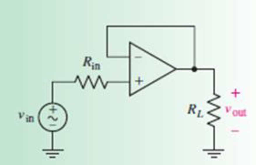
FIGURE 6.9
Expert Solution & Answer

Trending nowThis is a popular solution!

Students have asked these similar questions
Electrical Engineering
I need help, thank you.
Given the isolated inverse-SEPIC converter operating In CCM of fig. 6.39 shown here:
D, *
C= R
There are two inductors in this converter, The magnetizing inducatnce and L2. By performing volt second balance for the magentizing inductance and L2, one can derive the steady state
duty cycle along with the steady state voltage across C1, VCi, in terms of the steady state output voltage, V. There are two cquations with two unknowns resulting from the two volt
second balance equations. Small ripple approximations are valid. What is the the input to output voltage ratio (v/vg)?
V
D
V
1-Dn
O V
D
V
1-D
O V
D
V
1-D
O v
V
1-Dn
Reee
Example 6.19, Fig. 6.33 (i) and Fig. 6.33 (ii) show the centre-tap and bridge type circuits
having the same load resistance and transformer turn ratio. The primary of each is connected to
230V, 50 Hz supply.
(i) Find the d.c. voltage in each case.
(ii) PIV for each case for the same d.c. output. Assume the diodes to be ideal.
5:1
5:1
100 Q
100 2
ww
230 V
230 V
(ii)
(i)
Fig. 6.33
రంరరర రర
రాారర్థజరరర
A
1) Consider the circuit at right, consisting of two
LEDS (one red, one green), which you can model
as “practical diodes" with VD= 2.0V (LEDS
typically have larger VD's than ordinary Si or Ge
diodes).
R
red
green
B
a) If terminals A and B were connected to a DC source with voltage Vo, what
would happen? (Consider applying in both polarities, i.e. +Vo and –Vo, and
when VoVD...)
b) If the terminals A and B were connected to an AC source with peak voltage
VO, what would happen? (Consider both very low frequency: f<~1 Hz –
and high-frequency cases.)
c) If R = 1 k2, and both diodes have a maximum continuous power dissipation
of 0.1 W and a peak inverse voltage VPIV = 20V, what is the maximum DC
voltage VDCmax which can be safely applied between A and B?
Chapter 6 Solutions
Loose Leaf for Engineering Circuit Analysis Format: Loose-leaf
Ch. 6.2 - Derive an expression for vout in terms of vin for...Ch. 6.2 - Prob. 2PCh. 6.3 - An historic bridge is showing signs of...Ch. 6.4 - Design a circuit that provides a 12 V output if a...Ch. 6.4 - Design a noninverting Schmitt trigger that that...Ch. 6.5 - Assuming a finite open-loop gain (A), a finite...Ch. 6.5 - Use SPICE to simulate a voltage follower using an...Ch. 6 - For the op amp circuit shown in Fig. 6.39,...Ch. 6 - FIGURE 6.39 Determine the power dissipated by a...Ch. 6 - For the circuit of Fig. 6.40, calculate vout if...
Ch. 6 - For the circuit in Fig. 6.40, find the values of...Ch. 6 - (a) Design a circuit which converts a voltage...Ch. 6 - Prob. 6ECh. 6 - For the circuit of Fig. 6.40, R1 = RL = 50 ....Ch. 6 - Prob. 8ECh. 6 - (a) Design a circuit using only a single op amp...Ch. 6 - Prob. 11ECh. 6 - Determine the output voltage v0 and the current...Ch. 6 - Prob. 13ECh. 6 - Prob. 14ECh. 6 - Prob. 15ECh. 6 - Prob. 16ECh. 6 - Consider the amplifier circuit shown in Fig. 6.46....Ch. 6 - Prob. 18ECh. 6 - Prob. 19ECh. 6 - Prob. 20ECh. 6 - Referring to Fig. 6.49, sketch vout as a function...Ch. 6 - Repeat Exercise 21 using a parameter sweep in...Ch. 6 - Obtain an expression for vout as labeled in the...Ch. 6 - Prob. 24ECh. 6 - Prob. 25ECh. 6 - Prob. 26ECh. 6 - Prob. 27ECh. 6 - Prob. 28ECh. 6 - Prob. 29ECh. 6 - Prob. 30ECh. 6 - Prob. 31ECh. 6 - Determine the value of Vout for the circuit in...Ch. 6 - Calculate V0 for the circuit in Fig. 6.55. FIGURE...Ch. 6 - Prob. 34ECh. 6 - The temperature alarm circuit in Fig. 6.56...Ch. 6 - Prob. 36ECh. 6 - For the circuit depicted in Fig. 6.57, sketch the...Ch. 6 - For the circuit depicted in Fig. 6.58, (a) sketch...Ch. 6 - For the circuit depicted in Fig. 6.59, sketch the...Ch. 6 - In digital logic applications, a +5 V signal...Ch. 6 - Using the temperature sensor in the circuit in...Ch. 6 - Examine the comparator Schmitt trigger circuit in...Ch. 6 - Design the circuit values for the single supply...Ch. 6 - For the instrumentation amplifier shown in Fig....Ch. 6 - A common application for instrumentation...Ch. 6 - (a) Employ the parameters listed in Table 6.3 for...Ch. 6 - Prob. 49ECh. 6 - For the circuit of Fig. 6.62, calculate the...Ch. 6 - Prob. 51ECh. 6 - FIGURE 6.63 (a) For the circuit of Fig. 6.63, if...Ch. 6 - The difference amplifier circuit in Fig. 6.32 has...Ch. 6 - Prob. 55ECh. 6 - Prob. 56ECh. 6 - Prob. 57ECh. 6 - Prob. 58ECh. 6 - Prob. 59ECh. 6 - Prob. 60ECh. 6 - A fountain outside a certain office building is...Ch. 6 - For the circuit of Fig. 6.44, let all resistor...
Additional Engineering Textbook Solutions
Find more solutions based on key concepts
How many coulombs do 93.8 1016 electrons represent?
Principles Of Electric Circuits
Analog Voltmeter Design Figure P2-98(a) shows a voltmeter circuit consisting of a D'Arsonval meter, two series ...
ANALYSIS+DESIGN OF LINEAR CIRCUITS(LL)
Identify the type of input and output configuration for each diff-amp in Figure 18-35.
Electronics Fundamentals: Circuits, Devices & Applications
Design an ideal inverting op-amp circuit such that the voltage gain is Av=25 . The maximum current in any resis...
Microelectronics: Circuit Analysis and Design
The current source in the circuit shown generates the current pulse
Find (a) v (0); (b) the instant of time gr...
Electric Circuits. (11th Edition)
Assume a telephone signal travels through a cable at two-thirds the speed of light. How long does it take the s...
Electric Circuits (10th Edition)
Knowledge Booster


Learn more about
Need a deep-dive on the concept behind this application? Look no further. Learn more about this topic, electrical-engineering and related others by exploring similar questions and additional content below.Similar questions
- Some electronic devices operate on a DC voltage of 7.5 V. To obtain 7.5 V DC from a 120-V (rms) AC line, first the voltage is dropped to 7.5 V (rms) AC by a transformer, and then the 7.5 V AC is converted to 7.5 V DC by a rectifier circuit involving diodes. Consider a device of resistance 15 Ω connected to the 7.5-V DC output of the rectifier. Again assuming no power loss anywhere, what is the rms current, in milliamperes, in the primary winding?arrow_forwardOne can assemble a “virtual” solar cell array by using playing cards, or business or index cards, to represent a solar cell. Combinations of these cards in series and/or parallel can model the required array output. a) Assume each card has an output of 0.5 V and a current (under bright light) of 2 A. Using your cards, how would you arrange them to produce an output of 6 A at 3 V (i.e. - 18 W)? b) Suppose you were told that you needed only 18 W (but no required voltage). Would you need more cards to make this arrangement?arrow_forward3. A half-wave rectifier with a 200 load resistor operates from a 120 Vrms 60 Hz household supply current through a 6-to-1 step-down transformer. It uses a silicon diode that can be modelled as having a Vƒ = 0.9 V drop for any current. > vs(t) VL (t) www RL (a) What is the peak voltage, US,peak, of the secondary? What is the peak voltage, UL,peak of the rectified output? (b) For what fraction of the cycle (in percentage) does the diode conduct? (c) What is the average output voltage, V₁? (d) What is the average output current, IL? (e) What size of capacitor should you add across the output to provide a peak-to-peak ripple voltage, Vr, of 10% of the peak output?arrow_forward
- A battery is comprised of 4 cells connected in parallel, each cell has an EMF with 1.2V and an internal resistance of 0.55 ohm. There is no load connected to the terminals. Solve for Vterm.arrow_forwardA 6-uF and a 10-uF capacitor is connected in parallel are in series with a 12-uF capacitor. The combination, is then connected across 250 Volts source. Determine (a) charge in each capacitor; (b) total energy; (c) energy in 6-uF capacitor; (d) energy in 10-uF capacitor; (e) energy in 12-uF capacitor. 6 µF 10 µF 250 C = 6.857 uF; Q = 1.714 mC (a) Q1 = 643 uC; Q2 = 1.07 uC; Q, = 1.714 uC; (b) W= 0.214 J; (c) W,=0.034 J; (d) W, = 0.057 J; (e) W, = 0.123 J *12 µFarrow_forwardA 6-uF and a 10-uF capacitor is connected in parallel are in series with a 12-uF capacitor. The combination is then connected across 250 Volts source. Determine (a) charge in each capacitor; (b) total energy; (c) energy in 6-uF capacitor; (d) energy in 10-uF capacitor; (e) energy in 12-uF capacitor. 6 uF 10 µF 250 *12 Farrow_forward
- A 6-uF and a 10-uF capacitor is connected in parallel are in series with a 12-uF capacitor. The combination is thenconnected across 250 Volts source. Determine (a) charge in each capacitor;(b) total energy; (c) energy in 6-uF capacitor; (d) energy in 10-uF capacitor;(e) energy in 12-uF capacitor.arrow_forwardWith a D'Arsonval movement with 200 internal resistance and 100 mA FSD current, it is required to design an ammeter with a current ranges of 0.5 A, 3 A, and 5 A by using Ayrton shunt. Therefore, Rsh1 = Rhs2=............. Rh3=............arrow_forwardOne can assemble a “virtual” solar cell array by using playing cards, or business or index cards, to represent a solar cell. Combinations of these cards in series and/or parallel can model the required array output. Assume each card has an output of 0.5 V and a current (under bright light) of 2 A. Using your cards, how would you arrange them to produce an output of 6 A at 3 V (18 W)?Suppose you were told that you needed only 18 W (but no required voltage). Would you need more cards to make thisarrangement?arrow_forward
- Q6.) Identify whether the following statement are true(T) or false (F) 1- Persistence is the propriety of some crystalline material such as phosphor or zinc oxide to emit light when simulates by radiation. 2- If at one end, the two wires made of different metals are joined together then a Voltage will get produced between the two wires due to difference of temp between the two ends of wires. This effect is observed in thermocouples. 3- The temperature of a furnace can be measured by radiation pyrometer. 4- A piezo-electrical transducer is an example for active transducer. 5- The (1) is remove form control register in successive approximation DVM when (Vin) is greater than VD (A/D convertor voltage).arrow_forwardFind the output voltage of the Wheatstone bridge when resistance of RTD is 2500, if PTRTD is used for measurement process. 1000 Assume vin = 5v and all arms have equal resistance at initial condition. (Write at least the formula and final answer) %3Darrow_forwardQ6) Consider a silicon sample is doped with 1015/cm³ Arsenic(As),then additionally doped with Boron(B) 1017/cm³.Calculate the total conductivity of the material .What is the type of the net sample Assume: H,= 560 cm²/V-S, µ-950 cm²/V-S, n= 1.5x1010 cm²/V-S,and q=1.6x10⁻¹⁹C. onarrow_forward
arrow_back_ios
SEE MORE QUESTIONS
arrow_forward_ios
Recommended textbooks for you
 Introductory Circuit Analysis (13th Edition)Electrical EngineeringISBN:9780133923605Author:Robert L. BoylestadPublisher:PEARSON
 Delmar's Standard Textbook Of ElectricityElectrical EngineeringISBN:9781337900348Author:Stephen L. HermanPublisher:Cengage Learning
 Programmable Logic ControllersElectrical EngineeringISBN:9780073373843Author:Frank D. PetruzellaPublisher:McGraw-Hill Education
 Fundamentals of Electric CircuitsElectrical EngineeringISBN:9780078028229Author:Charles K Alexander, Matthew SadikuPublisher:McGraw-Hill Education
 Electric Circuits. (11th Edition)Electrical EngineeringISBN:9780134746968Author:James W. Nilsson, Susan RiedelPublisher:PEARSON
 Engineering ElectromagneticsElectrical EngineeringISBN:9780078028151Author:Hayt, William H. (william Hart), Jr, BUCK, John A.Publisher:Mcgraw-hill Education,
Introductory Circuit Analysis (13th Edition)
Electrical Engineering
ISBN:9780133923605
Author:Robert L. Boylestad
Publisher:PEARSON
Delmar's Standard Textbook Of Electricity
Electrical Engineering
ISBN:9781337900348
Author:Stephen L. Herman
Publisher:Cengage Learning
Programmable Logic Controllers
Electrical Engineering
ISBN:9780073373843
Author:Frank D. Petruzella
Publisher:McGraw-Hill Education
Fundamentals of Electric Circuits
Electrical Engineering
ISBN:9780078028229
Author:Charles K Alexander, Matthew Sadiku
Publisher:McGraw-Hill Education
Electric Circuits. (11th Edition)
Electrical Engineering
ISBN:9780134746968
Author:James W. Nilsson, Susan Riedel
Publisher:PEARSON
Engineering Electromagnetics
Electrical Engineering
ISBN:9780078028151
Author:Hayt, William H. (william Hart), Jr, BUCK, John A.
Publisher:Mcgraw-hill Education,
Peripheral Pin Select (PPS) for Microchip 8-bit PIC MCU; Author: Microchip Technology;https://www.youtube.com/watch?v=tf2SfSm6fQg;License: Standard Youtube License