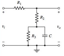
For the circuit shown in Figure P7.12, the parameters are R 1 = 10 kΩ , R 2 = 10 kΩ , R 3 = 40 kΩ , and C = 10 μF . (a) What is the value of the voltage transfer function V o / V i at very low frequencies? (b) Determine the value of the voltage transfer function at very high frequencies. (c) Derive the expression for the voltage transfer function T ( s ) = V o ( s ) / V i ( s ) . Put the expression in the form T ( s ) = K ( 1 + s τ A ) / ( 1 + s τ B ) . What are the values of K , τ A , and τ B ? Figure P7.12
For the circuit shown in Figure P7.12, the parameters are R 1 = 10 kΩ , R 2 = 10 kΩ , R 3 = 40 kΩ , and C = 10 μF . (a) What is the value of the voltage transfer function V o / V i at very low frequencies? (b) Determine the value of the voltage transfer function at very high frequencies. (c) Derive the expression for the voltage transfer function T ( s ) = V o ( s ) / V i ( s ) . Put the expression in the form T ( s ) = K ( 1 + s τ A ) / ( 1 + s τ B ) . What are the values of K , τ A , and τ B ? Figure P7.12
Solution Summary: The author explains the value of voltage transfer function at low frequency.
For the circuit shown in Figure P7.12, the parameters are
R
1
=
10
kΩ
,
R
2
=
10
kΩ
,
R
3
=
40
kΩ
, and
C
=
10
μF
. (a) What is the value of the voltage transfer function
V
o
/
V
i
at very low frequencies? (b) Determine the value of the voltage transfer function at very high frequencies. (c) Derive the expression for the voltage transfer function
T
(
s
)
=
V
o
(
s
)
/
V
i
(
s
)
. Put the expression in the form
T
(
s
)
=
K
(
1
+
s
τ
A
)
/
(
1
+
s
τ
B
)
. What are the values of K,
τ
A
, and
τ
B
?
This is a practice question from my Introduction to Circuits course.
I am having a hard time finding the poles for this. When I implement the circuit in LT Spice, I can see that the cutoff frequency is somewhere around 16kHz, but I can't figure out how to come up with that value mathematically. It is underdamped; so, will have imaginary components, but I'm lost as to how to find them or what to do with them or how to come up with the correct cutoff frequency to match LT Spice.
Thank you for your assistance.
What is the z-transfer function of the system
ASAP
It is a type of diode where it operates as a variable resistor when heated.
Your answer
What is the modulation index in ideal condition of AM.
Your answer
A form of AM where a sideband is filtered after its carrier is eliminated.
Your answer
What is the form of AM that used to transmit video signals of the TV system?
Your answer
It is a circuit in the superheterodyne receiver that adds and subtracts the frequencies of the AM signal and the local oscillator frequency.
It is the extent to which the amplitude of the carrier wave is varied by modulating wave.
Need a deep-dive on the concept behind this application? Look no further. Learn more about this topic, electrical-engineering and related others by exploring similar questions and additional content below.


 Introductory Circuit Analysis (13th Edition)Electrical EngineeringISBN:9780133923605Author:Robert L. BoylestadPublisher:PEARSON
 Delmar's Standard Textbook Of ElectricityElectrical EngineeringISBN:9781337900348Author:Stephen L. HermanPublisher:Cengage Learning
 Programmable Logic ControllersElectrical EngineeringISBN:9780073373843Author:Frank D. PetruzellaPublisher:McGraw-Hill Education
 Fundamentals of Electric CircuitsElectrical EngineeringISBN:9780078028229Author:Charles K Alexander, Matthew SadikuPublisher:McGraw-Hill Education
 Electric Circuits. (11th Edition)Electrical EngineeringISBN:9780134746968Author:James W. Nilsson, Susan RiedelPublisher:PEARSON
 Engineering ElectromagneticsElectrical EngineeringISBN:9780078028151Author:Hayt, William H. (william Hart), Jr, BUCK, John A.Publisher:Mcgraw-hill Education,