
Concept explainers
Videos
With regard to the circuit presented in Fig. 9.42, (a) obtain an expression for v(t) which is valid for all t > 0; (b) calculate the maximum inductor current and identify the time at which it occurs; (c) determine the settling time.
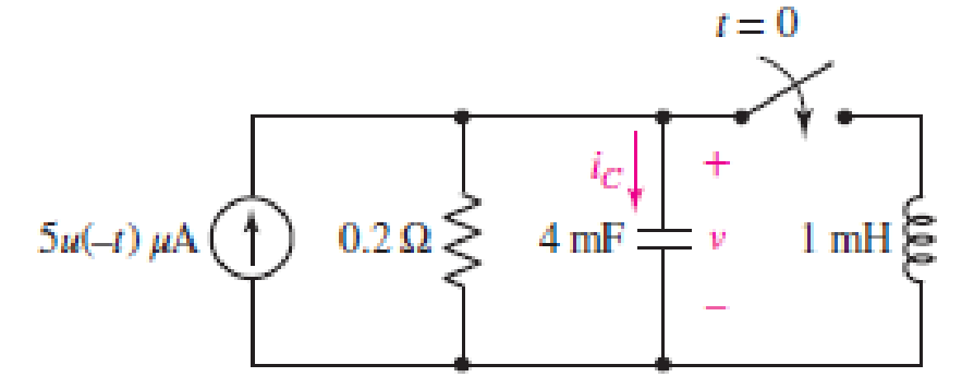
FIGURE 9.42
(a)
Find the equation for voltage
Answer to Problem 16E
The equation of voltage is
Explanation of Solution
Formula used:
The expression for the exponential damping coefficient is as follows:
Here,
The expression for the resonating frequency is as follows:
Here,
The expression for the two solutions of the characteristic equation of a parallel
Here,
Here,
Calculation:
The redrawn circuit is shown in Figure 1 as follows:
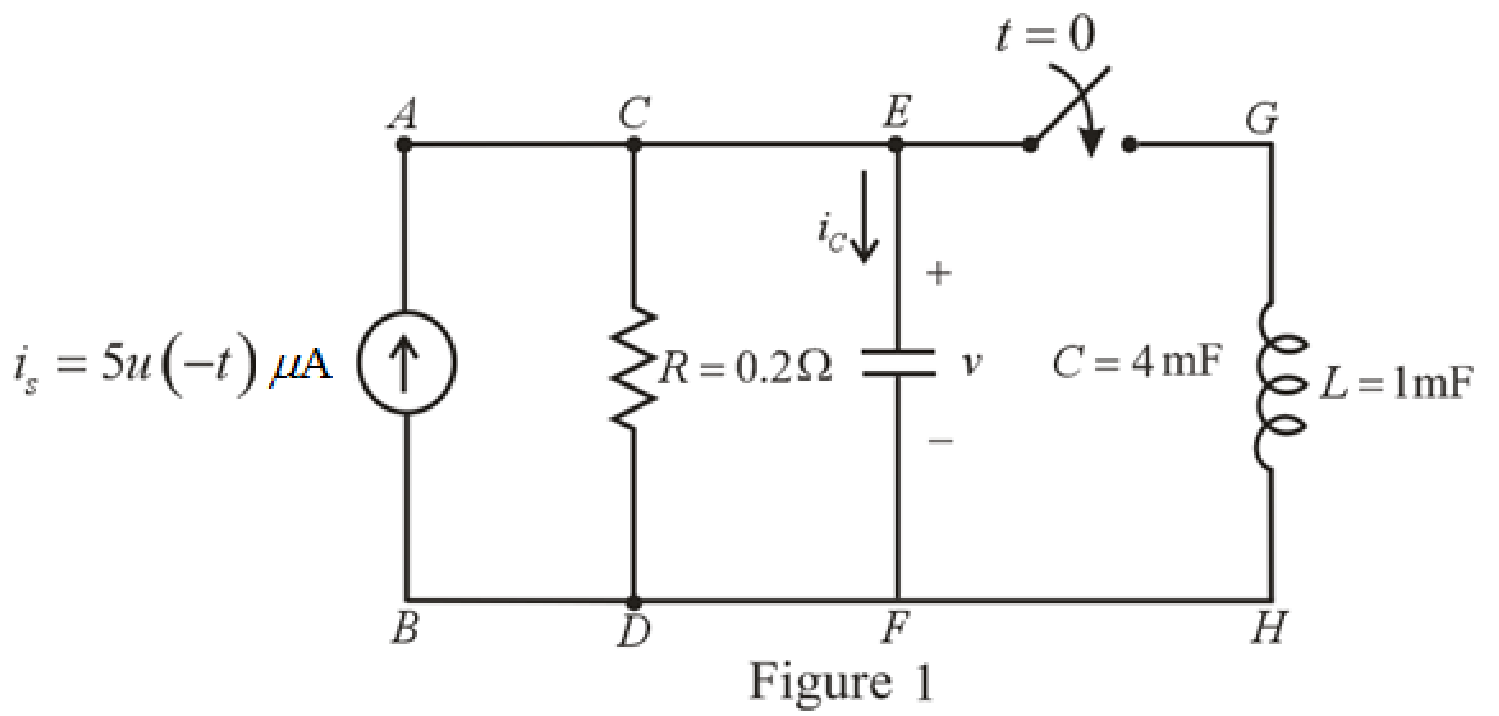
Refer to the Figure 1,
At
The current across inductor is zero because inductor is not energized.
The expression for voltage
Here,
The redrawn circuit at
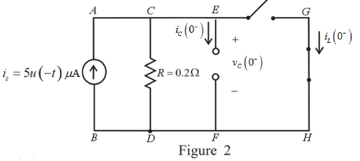
Refer to the Figure 2:
The expression for the voltage across capacitor at
Substitute
The expression for the natural response of voltage for capacitor in the parallel
Substitute
Rearrange for
At
Therefore,
So,
The redrawn circuit is shown in Figure 3 as follows:
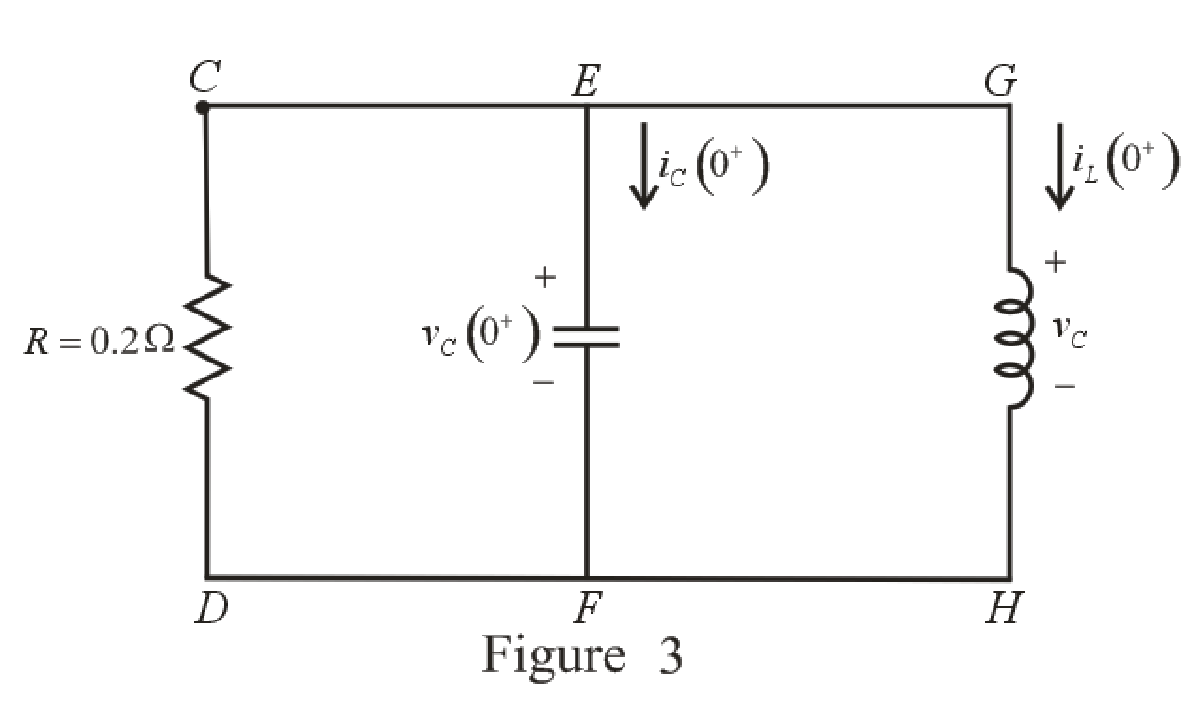
Refer to the Figure 3:
The current across resistor
The expression for KCL at node
Here,
Substitute
The expression for current flowing through capacitor for
Here,
At
The circuit diagram is redrawn as shown in Figure 4 for
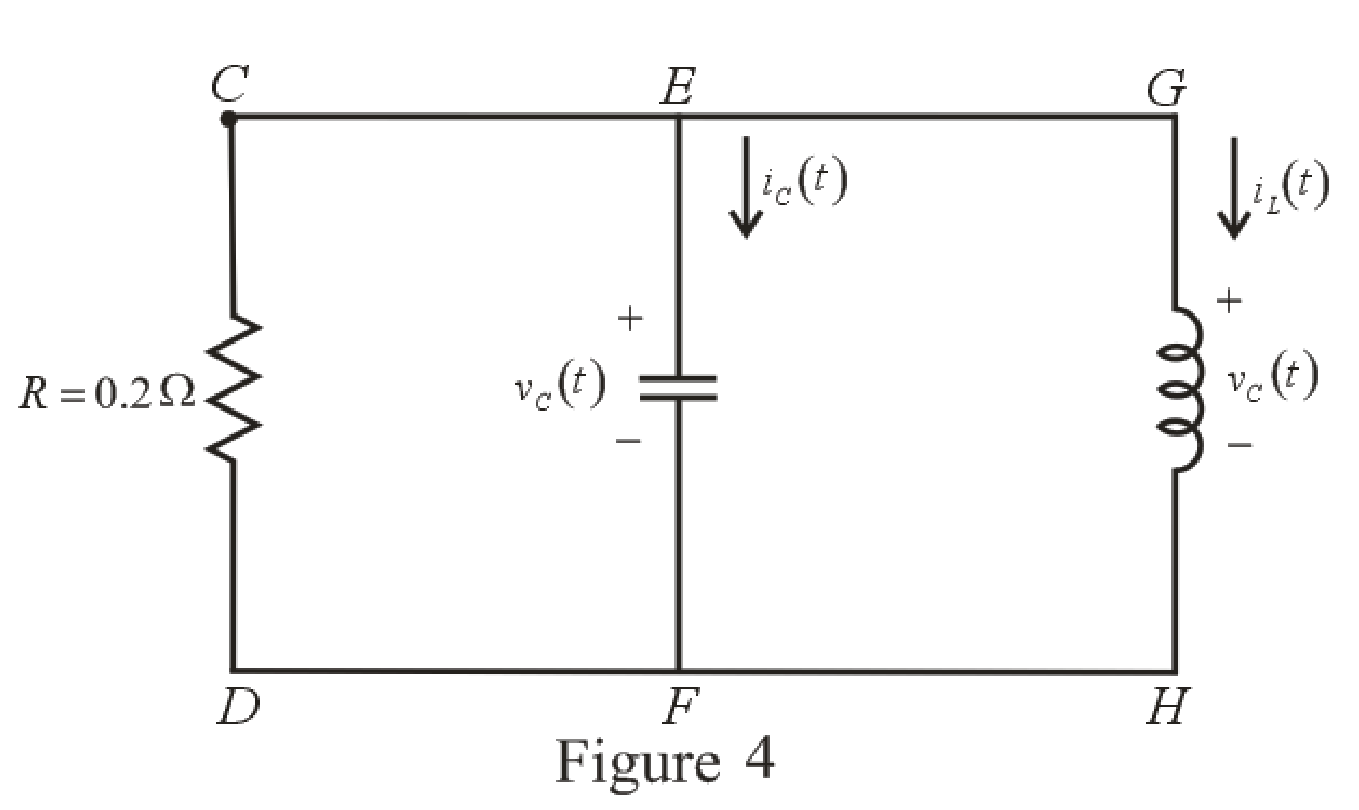
Refer to the redrawn Figure 4:
Substitute
Substitute
As value of exponential frequency
Substitute
Substitute
Differentiate equation (6) both the sides with respect to time
Substitute
Substitute
Substitute
Rearrange for
Rearrange for
Substitute
Substitute
Therefore, voltage across inductor
Conclusion:
Thus, the voltage
(b)
Find the maximum inductor current and the time of occurrence.
Answer to Problem 16E
The maximum inductor current
Explanation of Solution
Calculation:
Refer to the Figure 4:
The expression for inductor current is:
Substitute
For the maximum positive value of inductor current, take the derivative of its equation and then, equate it to zero to find the time at which maximum value of current occurs.
Differentiate equation (14) both the sides with respect to time
Equate the equation to zero.
Rearrange the equation.
Take log both the sides.
Rearrange for
Substitute
This is the maximum inductor current.
Conclusion:
Thus, the maximum inductor current is
(c)
Find the settling time.
Answer to Problem 16E
The settling time of the voltage
Explanation of Solution
Calculation:
The settling time is the time at which inductor current reaches to
Substitute
The settling time is the time at which the inductor current is decreased to
Equation (17) is solved by scientific calculator which can determine the value of time
Conclusion:
Thus, the settling time of the inductor current
Want to see more full solutions like this?
Chapter 9 Solutions
Engineering Circuit Analysis


- 9.pdf - Adobe Acrobat Reader DC (64-bit) ndow Help FINAL EP QP_SEM . x Sign In 10 / 12 116% Search Combine PDF Export PDF A capacitor is charged with 50 mC in a time of 20 uS. If the energy stored in the capacitor is 5 J, Edit PDF find (i) voltage across the capacitor, (ii) current through the capacitor and (iii) value of capacitance. Create PDF EComment Combine Files E0 Organize Pag Delete, insert, extract and rotate pages. Try now Convert, edit and e-sign Parrow_forward9. 7.92. b) Suppose the inductor you chose in part (a) has an initial currentof 10 mA. Write an expression for the current through the inductorfor t≥0.arrow_forward3. We have seen that in a series RLC circuit, Kirchoff's voltage law (VR +VL + Vc = Vs, where Vs is the supply voltage) leads to a 2nd order differential equation for the current I(t). Let us now consider a parallel RLC circuit consisting of a 5 H inductor, a 10 F capacitor, and a 0.5 N resistor. At time t = 0 s, there is a supply current Is of 5 A. The supply voltage Vs is common to all three components. Kirchoff's current law states that IR + IL + Iç = Is.arrow_forward
- S:46) I just need the integral of the mutual inductance for these 3 problemsarrow_forwardQ1 (True/False): A) The current through the capacitor is inversely proportional to the derivative of the voltage across it: Is it true or false? B) In a typical electronic circuit the capacitor blocks DC and couplest he AC to the next stage of the circuit: Is it true or false? C) The more the value of the stray capacitance , the better it is: Is it true or false?arrow_forwardThe ac bridge shown in Fig. 9.84 is known as a Maxwell bridge and is used for accurate measurement of inductance and resistance of a coil in terms of a standard capacitance C.. Show that when the bridge is balanced, R2 R3 R₁ Lx = R₂R3Cs and Rx = 1.6 ΚΩ, Find Lx and R, for R₁ = 40 kN, R₂ R3 = 4 kn, and C₂ = 0.45 µF. R₁ R3 Cs R₂ AC meter R₂ ellarrow_forward
- Find and plot the currents i(t), iz(t), and iz(t) in the circuit below given is(t) as shown in the plot. Hint: First determine the equivalent inductance that can replace the three inductors. Next, find the voltage across the current source, then, calculate the current in each inductor. is (t) 1Hi(t) 10 mA Dis(t) ist) 5 H 3 is(t) 2 ms 4 msarrow_forwardYou are investigating the electrical testing circuits and find that, in an inductive circuit, the relationship between instantaneous current i (amps) and the time t (secs) is given by: i = 2.1(1-e-9t) You have been asked to determine the time taken for the current to rise from 1 to 1.5 amps. Comment on the time taken for the current to rise the same increment from 1.5 to 2 amps and give reasons.arrow_forwardA series circuit has a capacitor of 1.5625x10^(-8)F a resistor of 2x10^4 ohms, and an inductor of 1H. If the initial charge on the capacitor is zero,. if a 12-volt battery is connected to the circuit and the circuit is closed at t=0, determine the charge on the capacitor at any time tarrow_forward
- 2. A capacitor having a capacitance of 2.0 µF consists of two metal elec- trodes separated by an insulating spacer made of crystalline silicon. Silicon is a semiconductor, having a conductivity of 1.6x10⁻³ S/m and dielectric constant of 11.7. The capacitor is placed in a series with a 12 volt battery in a closed loop circuit. When steady state is reached, what is the charge on the capacitor, and what is the current in the circuit?arrow_forwardProblen the following: A. The voltage across the capacitor at the t = 0. B. The voltage across the capacitor for t > 0. C. The voltage across the 32K resistor for t > 0. Given RC circuit with a switch that moves from position A to B at time t =0 obtainarrow_forwardThe current through a 20-mH inductor is shown in Fig. 9. Sketch the voltage across the inductor. i(t) (A) 10 -10 0 1 2 Figure 9 3 4arrow_forward
 Introductory Circuit Analysis (13th Edition)Electrical EngineeringISBN:9780133923605Author:Robert L. BoylestadPublisher:PEARSON
 Delmar's Standard Textbook Of ElectricityElectrical EngineeringISBN:9781337900348Author:Stephen L. HermanPublisher:Cengage Learning
 Programmable Logic ControllersElectrical EngineeringISBN:9780073373843Author:Frank D. PetruzellaPublisher:McGraw-Hill Education
 Fundamentals of Electric CircuitsElectrical EngineeringISBN:9780078028229Author:Charles K Alexander, Matthew SadikuPublisher:McGraw-Hill Education
 Electric Circuits. (11th Edition)Electrical EngineeringISBN:9780134746968Author:James W. Nilsson, Susan RiedelPublisher:PEARSON
 Engineering ElectromagneticsElectrical EngineeringISBN:9780078028151Author:Hayt, William H. (william Hart), Jr, BUCK, John A.Publisher:Mcgraw-hill Education,