
Videos
For the circuit of Fig. 9.45, is(t) = 30u(−t) mA. (a) Select R1 so that v(0+) = 6 V. (b) Compute v(2 ms). (c) Determine the settling time of the capacitor voltage. (d) Is the inductor current settling time the same as your answer to part (c)?
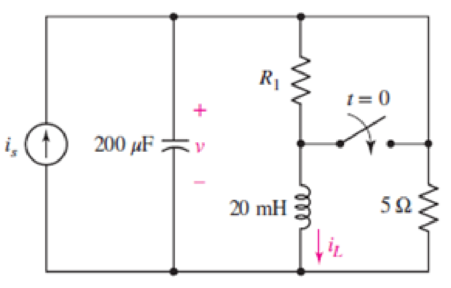
FIGURE 9.45
(a)
Select
Answer to Problem 26E
The resistance
Explanation of Solution
Given Data:
Formula used:
The expression for the exponential damping coefficient or the neper frequency is as follows:
Here,
The expression for the resonant frequency is as follows:
Here,
The expression for a critically damped response of a source free parallel RLC circuit is as follows:
Here,
Calculation:
The unit-step forcing function as a function of time which is zero for all values of its argument less than zero and which is unity for all positive values of its argument.
Here,
So, at
The redrawn circuit diagram is given in Figure 1 at
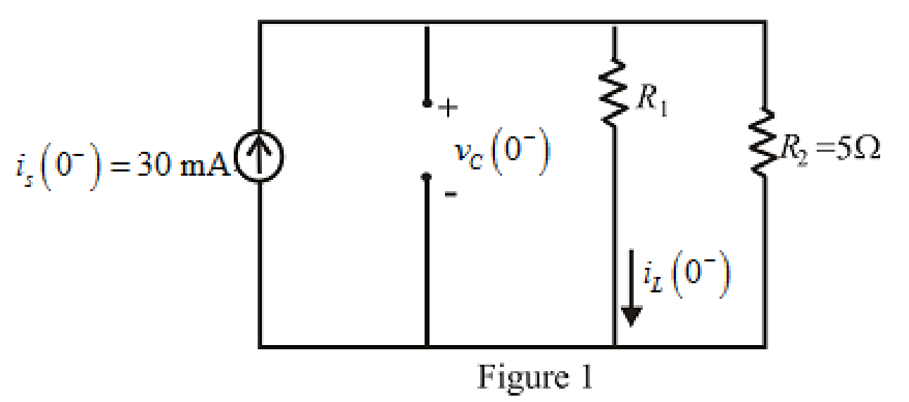
Refer to the redrawn Figure 1:
The expression for the current through the inductor at
Here,
The expression for the voltage across the capacitor at
Here,
Substitute
The capacitor does not allow sudden change in the voltage, so,
The voltage across the capacitor at
Substitute
Rearrange for
The resistance cannot be negative so, the resistance
Conclusion:
Thus, the resistance
(b)
Compute
Answer to Problem 26E
The value of the voltage
Explanation of Solution
Given data:
The time is
Calculation:
Substitute
The inductor does not allow sudden change in the current.
So,
So the current through inductor at
The redrawn circuit diagram is given in Figure 2 at
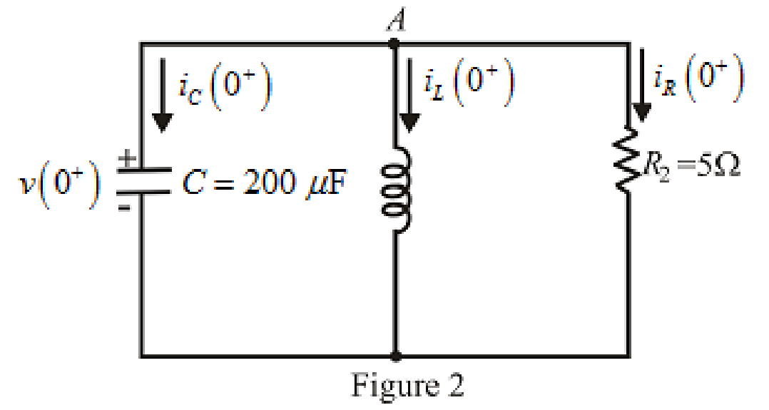
Refer to the redrawn Figure 2:
The expression for the current flowing in the
Here,
Substitute
Apply KCL at node
Here,
Substitute
Rearrange for
Substitute
Substitute
Substitute
Substitute
The voltage across the capacitor at
Substitute
Rearrange for
The expression for the current flowing through the
Substitute
Rearrange for
Substitute
The current flowing through the
Substitute
Substitute
Rearrange for
Substitute
Substitute
Conclusion:
Thus, the value of the voltage
(c)
Determine the settling time of the capacitor voltage.
Answer to Problem 26E
The settling time of the capacitor voltage is
Explanation of Solution
Calculation:
The maximum voltage appears across the capacitor at
So, for maximum voltage,
Substitute
Settling time is the time at which the value of the voltage reaches
The expression for the voltage at
Here,
Substitute
Substitute
The value of
Conclusion:
Thus, the settling time of the capacitor voltage is
(d)
Is the inductor current settling time the same as your answer to part (c)?
Answer to Problem 26E
The inductor current settling time is not same as capacitor voltage settling time.
Explanation of Solution
Calculation:
The expression for the current through inductor is as follows:
Here,
Substitute
Simplify further.
The maximum current through the inductor is at
So, for the maximum current,
Substitute
Settling time is the time at which the value of the current reaches
The expression for the current at
Here,
Substitute
Substitute
Rearrange equation (22).
The value of
So the inductor current settling time is
Conclusion:
Thus, the inductor current settling time is not same as capacitor settling time.
Want to see more full solutions like this?
Chapter 9 Solutions
Engineering Circuit Analysis


- P 9.7-1 Determine the forced response for the inductor current it when (a) is = 3 A, (b) is = 1.5t A, and (c) is = 6e-7501 A for the circuit of Figure P 9.7-1. is u(1) A Figure P 9.7-1 300/1952 30 mH 3 mFarrow_forward9798 "For a practical inductor, the current leads the voltage by an angle of less than 90 degrees." True False "By practice, an ideal capacitor does not model a practical capacitor quite accurately." True Falsearrow_forward! Required information Problem 06.001 - DEPENDENT MULTI-PART PROBLEM - ASSIGN ALL PARTS The voltage across a 10-F capacitor is 2te-3t V. NOTE: This is a multi-part question. Once an answer is submitted, you will be unable to return to this part. Problem 06.001.a - Current through a capacitor Find the current through the capacitor. The current through the capacitor is -3t A. |(1-3 t)e¯arrow_forward
- A multi-plate capacitor is made up of 501 sheets of aluminum 20 cm x 30 cm with an insulation of paraffin paper 0.0015 cm thick. What is the capacitance in microfarads of the capacitor? (k for paraffin paper is 3) a. 50 b. 55 c. 35 d. 67arrow_forwardConsider the circuit in figure given below: A B The capacitor C is initially charged. At time 0, the switch is connected from A to B and the voltage across the capacitor is measured. The following data are recorded by a data acquisition system: t(s) 0.0 0.1 0.2 0.3 0.4 0.5 V(V) 4.98 1.84 0.68 0.25 0.09 0.03 (a) Determine the linear correlation coefficient betweent and V. (b) Determine the linear correlation coefficient between t and In(V).arrow_forwardA parallel ac power circuit contains a resistor (R = 2002), an inductor, and a capacitor. Knowing that the source voltage Es is equal to 100 V and that the total reactive power Q in the circuit is 70.0 var, calculate the circuit impedance Z. A series ac power circuit contains a resistor (R = 150 M2), an inductor (X₂ = 250 ), and a capacitor (Xc = 200 22). Knowing that the active power P dissipated in the circuit is equal to 100 W, calculate the apparent power S in the circuit.arrow_forward
- 4) The function sin x (which you may remember from Calculus 1 limits) is important in signal processing and electrical engineering, and is known as the "sinc" function, often abbreviated as just sinc(x). Find § sinc(x) dx. Then, approximate ſ sinc(x) dx using the first five terms of the appropriate series.arrow_forwardThe following figure represents an RC-Circuit with the switch. In Figure A, the capacitor is initially uncharged. In Figure B, the capacitor is initially fully charged. 1) Draw and label the current direction immediately after the switch is closed for each figure. 2) Consider Figure A. What is the voltage across the capacitor as t → 0? Explain. 3) Consider Figure B. Is the voltage across the resistor increasing, decreasing or staying the same as t → 0? Explain. A) B) R Carrow_forwardFor the circuit in the figure, initially the switch S is closed in (b), until the capacitor is charged; then the switch goes to point (a) so that the battery is disconnected and the capacitor, resistor and inductor are connected in series. Once S is connected at point (a), find a) the angular frequency of oscillation for the series circuit b) write the equation for the charge on the capacitor as a function of time with the respective values of Qmax, angular frequency Wd and time T c) make the Q(t) graph showing explicitly the envelope of the exponential decay (Hint: use geogebra or an application of your choice to obtain a graph).arrow_forward
- Required information Problem 06.037 - DEPENDENT MULTI-PART PROBLEM - ASSIGN ALL PARTS The current through a 17-mH inductor is 4 sin 100t A. NOTE: This is a multi-part question. Once an answer is submitted, you will be unable to return to this part. Problem 06.037.b - Energy stored in an inductor Find the energy stored at t= S. 200 The energy stored is mJ.arrow_forwardeeeeee t=0 Y. Co) = 15V Ye C4) 0,25MF R In the above circuit, thie switch closes at t= 0. The capacitor is charged to voltage ISV initially. Find the capacitor for the following cases: Ca) R= 8.5k (6) R= 4k () R= 1k * plot the waveforms for each Cuse wwwarrow_forwardA 20-µF capacitor is connected in parallel to the series connection of a variable resistor R and a 100-mH inductor. The circuit is energized by a 120 Vac, 60-Hz suuply. Find the value of R such that the total circuit current is 1.167338/25.8339° A.arrow_forward
 Introductory Circuit Analysis (13th Edition)Electrical EngineeringISBN:9780133923605Author:Robert L. BoylestadPublisher:PEARSON
 Delmar's Standard Textbook Of ElectricityElectrical EngineeringISBN:9781337900348Author:Stephen L. HermanPublisher:Cengage Learning
 Programmable Logic ControllersElectrical EngineeringISBN:9780073373843Author:Frank D. PetruzellaPublisher:McGraw-Hill Education
 Fundamentals of Electric CircuitsElectrical EngineeringISBN:9780078028229Author:Charles K Alexander, Matthew SadikuPublisher:McGraw-Hill Education
 Electric Circuits. (11th Edition)Electrical EngineeringISBN:9780134746968Author:James W. Nilsson, Susan RiedelPublisher:PEARSON
 Engineering ElectromagneticsElectrical EngineeringISBN:9780078028151Author:Hayt, William H. (william Hart), Jr, BUCK, John A.Publisher:Mcgraw-hill Education,