
Loose Leaf for Engineering Circuit Analysis Format: Loose-leaf
9th Edition
ISBN: 9781259989452
Author: Hayt
Publisher: Mcgraw Hill Publishers
expand_more
expand_more
format_list_bulleted
Concept explainers
Videos
Textbook Question
Chapter A8, Problem 2P
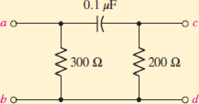
If a current source i1(t) = u(t) A is present at a-b in Fig. A8.9 with the arrow entering a, find H(s) = Vcd/I1, and specify the natural frequencies present in vcd (t).
Expert Solution & Answer
Want to see the full answer?
Check out a sample textbook solution
Students have asked these similar questions
3. Sketch the root locus for the unity feedback system
shown in Figure P8.3 for the following transfer
functions: [Section: 8.4]
K(s+2)(s+6)
s2 + 8s + 25
а. G(s)
K(s² + 4)
(s² + 1)
K(s² + 1)
b. G(s)
c. G(s) =
K
d. G(s) =
(s+1)°(s+4)
= 0.29 Determine the frequency response
Q1 A standard second order system has on =8.8 and
specifications w, and Mr and bandwidth. Also find number of oscillations before setting, in the
step response.
Signal Flow Graphs
Derive the transfer function for the signal flow graph shown Figure 8.
Y1
H5
H,
1
H
Y
H,
H3
13
Y5
H4
Figure 8: Signal flow graph
Chapter A8 Solutions
Loose Leaf for Engineering Circuit Analysis Format: Loose-leaf
Additional Engineering Textbook Solutions
Find more solutions based on key concepts
Design an ideal inverting op-amp circuit such that the voltage gain is Av=25 . The maximum current in any resis...
Microelectronics: Circuit Analysis and Design
Explain the main function of each of the following major components of a PLC: a. Processor module (CPU) b. I/O ...
Programmable Logic Controllers
The voltage source of the circuit shown in Fig. P1.29 is given by s(t)=25cos(4104t45)(V). Obtain an expression ...
Fundamentals of Applied Electromagnetics (7th Edition)
How many coulombs do 93.8 1016 electrons represent?
Principles Of Electric Circuits
Electric power systems provide energy in a variety of commercial and industrial settings. Make a list of system...
Principles and Applications of Electrical Engineering
Write the nodal equations for the network of Fig. 8.137 using the general approach. Find the nodal voltages usi...
Introductory Circuit Analysis (13th Edition)
Knowledge Booster


Learn more about
Need a deep-dive on the concept behind this application? Look no further. Learn more about this topic, electrical-engineering and related others by exploring similar questions and additional content below.Similar questions
- 81/ A. For the following Fyure Find I To tal, URI, VR2 Si3 1ov. R. 3 V 7:5 Q1/B- For the following Fiqure Find: VR3, VR2, IR2 , IR 4K 1ok R. fov 2KED3 a2/.Desiyn Circint as the following peseripton: A- the positive cycle of the vout signal is 3.2 and Negative cycle is 4.3 (Note: we must used preetical Diodes and vin is tov) 13- the positive cyclep of vout is 5:3 andd Negative cycle is (5. 4) [Note: Consider tovand we must used Cupaetor with praetical Diede) Vinarrow_forwardExercise: Find F=[sinc(S)] =? LET af farrow_forwardA control system is represented by the following differential equation; d2x/dt2 + 5dx/dt+7x =7y What will be the frequency of oscillation _________________ and the damping ratio ___________________ of the system respectively if the transfer function is X(s)/Y(s) fill the gaparrow_forward
- i. Briefly discuss the three types of responses in a series RLC circuit. Write down the conditions for the three responses in terms of the neper frequency, a, and undamped natural frequency (or resonant frequency), wo. ii. A series RLC circuit is connected to a voltage source that steps from 0V to 5V at t = 0s. The values ofL and C are 100mH and 0.1uF respectively, while R ranges from 200 Q to 5 k Q. Assume zero initial conditions. a. Write down the expression of the voltage across the capacitor for the three types of responses (for the three different values of R).arrow_forwardSolve for Vp and Vs. Show your complete solution. (When you try to simulate the circuit in LTSpice where (Vin=0 DC Offset, 10V amplitude, 1MHz frequency), Vp=8V and Vs=40V. I want to learn how to get these values by solving) Will upvote is complete solution and correct. Thank you.arrow_forward7:07 ull 3G Problems for h... Problems for homework 2 Q1. The block diagram of feedback control system shown in fig.s below find the transfer function C(s)/R(s). a) 3 R(s) 10 C(s) S+5 s(s + 1) 0.5s b) 5 R(s) C(s) 2s 2 Q2 . Apply the gain formula to the SFG shown in Figures land 2 to find the transfer function: ys/yı G. G. Y. H, Fig.1 -H Fig.2arrow_forward
- Q.1) Given the block diagram of a system shown in Figure below, find: 1. Convert the block diagram to a signal-flow graph. 2. Find the transfer function via signal-flow graph. G8(s) C(s) R(s) G1(s) Gs(s) G6(s) G2(s) G4(s) G7(3) G3(s)arrow_forward1-) Series and parallel; Transfer functions of RL,RC,RLC circuits , write the equations.arrow_forwardWhich signal-flow graph is adequate of the following block diagram? X(s). E(s) Y(s) H (s)arrow_forward
- Given the attenuation specifications shown. Design an RC op amp circuit with a Butterworth response in the passband. In your realization use only 0.1 µF capacitors. Also adjust the center-frequency gain of your circuit to be 1 (0 dB). a(o) dB 28 dB 28 dB 0.25 dB 100 200 300 600 o (rad/sec)arrow_forwardAnswer the following questions: a)" 1 Given the output voltage signal Vo(s) below, find the output voltage in the time domain vo(t). 2 Vo(s)= (s+2)(s+8) b) Discuss the application of Ohm's Law for a given R and C in series in both time and frequency domains. Files You can drag and drop files here to add them. Next pagearrow_forwardPlease give proper Circuit. Design a circuit with the following components; you can take any values. Vin is the input voltage. Vout is the output voltage. Rf and Cf are the feedback resistor and capacitor, respectively. R₁ and C; are the input resistor and capacitor, respectively.arrow_forward
arrow_back_ios
SEE MORE QUESTIONS
arrow_forward_ios
Recommended textbooks for you
 Introductory Circuit Analysis (13th Edition)Electrical EngineeringISBN:9780133923605Author:Robert L. BoylestadPublisher:PEARSON
 Delmar's Standard Textbook Of ElectricityElectrical EngineeringISBN:9781337900348Author:Stephen L. HermanPublisher:Cengage Learning
 Programmable Logic ControllersElectrical EngineeringISBN:9780073373843Author:Frank D. PetruzellaPublisher:McGraw-Hill Education
 Fundamentals of Electric CircuitsElectrical EngineeringISBN:9780078028229Author:Charles K Alexander, Matthew SadikuPublisher:McGraw-Hill Education
 Electric Circuits. (11th Edition)Electrical EngineeringISBN:9780134746968Author:James W. Nilsson, Susan RiedelPublisher:PEARSON
 Engineering ElectromagneticsElectrical EngineeringISBN:9780078028151Author:Hayt, William H. (william Hart), Jr, BUCK, John A.Publisher:Mcgraw-hill Education,
Introductory Circuit Analysis (13th Edition)
Electrical Engineering
ISBN:9780133923605
Author:Robert L. Boylestad
Publisher:PEARSON
Delmar's Standard Textbook Of Electricity
Electrical Engineering
ISBN:9781337900348
Author:Stephen L. Herman
Publisher:Cengage Learning
Programmable Logic Controllers
Electrical Engineering
ISBN:9780073373843
Author:Frank D. Petruzella
Publisher:McGraw-Hill Education
Fundamentals of Electric Circuits
Electrical Engineering
ISBN:9780078028229
Author:Charles K Alexander, Matthew Sadiku
Publisher:McGraw-Hill Education
Electric Circuits. (11th Edition)
Electrical Engineering
ISBN:9780134746968
Author:James W. Nilsson, Susan Riedel
Publisher:PEARSON
Engineering Electromagnetics
Electrical Engineering
ISBN:9780078028151
Author:Hayt, William H. (william Hart), Jr, BUCK, John A.
Publisher:Mcgraw-hill Education,
What is a Power Amplifier, And Do I Need One?; Author: Sweetwater;https://www.youtube.com/watch?v=2wkmSm4V00M;License: Standard Youtube License