
Loose Leaf for Engineering Circuit Analysis Format: Loose-leaf
9th Edition
ISBN: 9781259989452
Author: Hayt
Publisher: Mcgraw Hill Publishers
expand_more
expand_more
format_list_bulleted
Concept explainers
Videos
Textbook Question
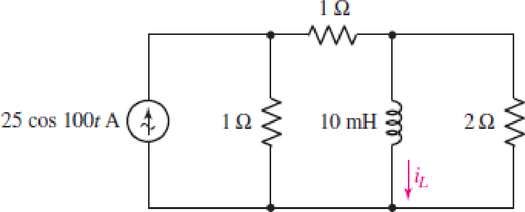
Chapter 10, Problem 11E
Assuming there are no longer any transients present, determine the current labeled iL in the circuit of Fig. 10.47. Express your answer as a single sinusoid.
FIGURE 10.47
Expert Solution & Answer
Want to see the full answer?
Check out a sample textbook solution
Students have asked these similar questions
For the circuit shown below, the reactive power delivered to the j10 ohms inductor is.VAR
10 2
-j5 2
100/0°
j10 Q
I) 60/30° V
none of the above
620
156
540
700 )
1200 )
120 ()
344 ()
ll
Answer each of these questions:
• If the voltage across a 24 F capacitor is 29 t e-3t V, calculate the power at t = 15 ms.
• What is the amplitude of the following sinusoidal voltage signal v(t) = 293 cos (374t + 250 ) V?
• What is the period of the following sinusoidal voltage signal v(t) = 229 cos (296t + 440 ) V?
• What is the frequency of the following sinusoidal voltage signal v(t) = 217 cos (190t + 370 ) V?
• What is the angular frequency of the following sinusoidal voltage signal v(t) = 102 cos (2011 + 710) V?
• What is the phase shift of the following sinusoidal voltage signal v(t): 194 cos (291t + 360 ) V?
=
• What is the value the following sinusoidal voltage signal v(t) = 275 cos (333t + 540 ) V at t = 63 s?
10:55 BYV
2.00 Yo 49
(48)
KB/S
Two coils are A and B ar :
Editing
9/7/21 10:55 AM
Two coils are A and B are
connected in series to a supply of
230V, 50HZ. Coil A has an
inductance of 0.2H and a
resistance of 20 Q, and coil B has
an inductance of 0.05H and a
resistance of 60 Q. Calculate the
current and its phase angle relative
to the supply voltage. Also
determine the voltage across each
coil.
|
Chapter 10 Solutions
Loose Leaf for Engineering Circuit Analysis Format: Loose-leaf
Ch. 10.1 - Find the angle by which i1 lags v1 if v1 = 120...Ch. 10.2 - Determine values for A, B, C, and if 40 cos(100t ...Ch. 10.2 - Let vs = 40 cos 8000t V in the circuit of Fig....Ch. 10.3 - Prob. 4PCh. 10.3 - If the use of the passive sign convention is...Ch. 10.4 - Let = 2000 rad/s and t = 1 ms. Find the...Ch. 10.4 - Transform each of the following functions of time...Ch. 10.4 - In the circuit of Fig. 10.17, both sources operate...Ch. 10.5 - With reference to the network shown in Fig. 10.19,...Ch. 10.5 - In the frequency-domain circuit of Fig. 10.21,...
Ch. 10.5 - Determine the admittance (in rectangular form) of...Ch. 10.6 - Use nodal analysis on the circuit of Fig. 10.23 to...Ch. 10.6 - Use mesh analysis on the circuit of Fig. 10.25 to...Ch. 10.7 - If superposition is used on the circuit of Fig....Ch. 10.7 - Prob. 15PCh. 10.7 - Determine the current i through the 4 resistor of...Ch. 10.8 - Select some convenient reference value for IC in...Ch. 10 - Evaluate the following: (a) 5 sin (5t 9) at t =...Ch. 10 - (a) Express each of the following as a single...Ch. 10 - Prob. 3ECh. 10 - Prob. 4ECh. 10 - Prob. 5ECh. 10 - Calculate the first three instants in time (t 0)...Ch. 10 - (a) Determine the first two instants in time (t ...Ch. 10 - The concept of Fourier series is a powerful means...Ch. 10 - Household electrical voltages are typically quoted...Ch. 10 - Prob. 10ECh. 10 - Assuming there are no longer any transients...Ch. 10 - Calculate the power dissipated in the 2 resistor...Ch. 10 - Prob. 13ECh. 10 - Prob. 14ECh. 10 - Prob. 15ECh. 10 - Express the following complex numbers in...Ch. 10 - Prob. 17ECh. 10 - Prob. 18ECh. 10 - Evaluate the following, and express your answer in...Ch. 10 - Perform the indicated operations, and express the...Ch. 10 - Insert an appropriate complex source into the...Ch. 10 - For the circuit of Fig. 10.51, if is = 2 cos 5t A,...Ch. 10 - In the circuit depicted in Fig. 10.51, if is is...Ch. 10 - Employ a suitable complex source to determine the...Ch. 10 - Transform each of the following into phasor form:...Ch. 10 - Prob. 26ECh. 10 - Prob. 27ECh. 10 - The following complex voltages are written in a...Ch. 10 - Assuming an operating frequency of 50 Hz, compute...Ch. 10 - Prob. 30ECh. 10 - Prob. 31ECh. 10 - Prob. 32ECh. 10 - Assuming the passive sign convention and an...Ch. 10 - The circuit of Fig. 10.53 is shown represented in...Ch. 10 - (a) Obtain an expression for the equivalent...Ch. 10 - Determine the equivalent impedance of the...Ch. 10 - (a) Obtain an expression for the equivalent...Ch. 10 - Determine the equivalent admittance of the...Ch. 10 - Prob. 40ECh. 10 - Prob. 41ECh. 10 - Find V in Fig. 10.55 if the box contains (a) 3 in...Ch. 10 - Prob. 43ECh. 10 - Prob. 44ECh. 10 - Design a suitable combination of resistors,...Ch. 10 - Design a suitable combination of resistors,...Ch. 10 - For the circuit depicted in Fig. 10.58, (a) redraw...Ch. 10 - For the circuit illustrated in Fig. 10.59, (a)...Ch. 10 - Referring to the circuit of Fig. 10.59, employ...Ch. 10 - In the phasor-domain circuit represented by Fig....Ch. 10 - With regard to the two-mesh phasor-domain circuit...Ch. 10 - Employ phasor analysis techniques to obtain...Ch. 10 - Determine IB in the circuit of Fig. 10.62 if and ....Ch. 10 - Determine V2 in the circuit of Fig. 10.62 if and ....Ch. 10 - Employ phasor analysis to obtain an expression for...Ch. 10 - Determine the current ix in the circuit of Fig....Ch. 10 - Obtain an expression for each of the four...Ch. 10 - Determine the nodal voltages for the circuit of...Ch. 10 - Prob. 59ECh. 10 - Obtain an expression for each of the four mesh...Ch. 10 - Determine the individual contribution each current...Ch. 10 - Determine V1 and V2 in Fig. 10.68 if I1 = 333 mA...Ch. 10 - Prob. 63ECh. 10 - Obtain the Thvenin equivalent seen by the (2 j) ...Ch. 10 - The (2 j) impedance in the circuit of Fig. 10.69...Ch. 10 - With regard to the circuit depicted in Fig. 10.70,...Ch. 10 - Prob. 67ECh. 10 - Determine the individual contribution of each...Ch. 10 - Determine the power dissipated by the 1 resistor...Ch. 10 - The source Is in the circuit of Fig. 10.75 is...Ch. 10 - Prob. 72ECh. 10 - (a) Calculate values for IL, IR, IC, VL, VR, and...Ch. 10 - In the circuit of Fig. 10.77, (a) find values for...Ch. 10 - The voltage source Vs in Fig. 10.78 is chosen such...Ch. 10 - For the circuit shown in Fig. 10.79, (a) draw the...Ch. 10 - For the circuit shown in Fig. 10.80, (a) draw the...Ch. 10 - (a) Replace the inductor in the circuit of Fig....Ch. 10 - Design a purely passive network (containing only...
Knowledge Booster


Learn more about
Need a deep-dive on the concept behind this application? Look no further. Learn more about this topic, electrical-engineering and related others by exploring similar questions and additional content below.Similar questions
- 10.29 The capacitor is initially charged to 6V with the polarity shown 4.7 k + 40 V "C a) Write the expression for the voltage vC after the switch is closed. b) Write the expression for the current iC after the switch if closed. C) Plot the results of a) and b)arrow_forwardA capacitor of 3.18 microfarads is connected in parallel with a resistance of 2000 ohms. The combination is further connected in series with an inductance of 795 mH and resistance of 100 ohms across a supply given by e=400 sin + 80 sin(3wt + 60O). Assume w = 314 rad/sec, determine the rms value of the total current.arrow_forward1. Convert the following to the corresponding to rectangular, phasor, and sinusoidal equivalents to fill in the table. Unless otherwise specified, consider the frequency to be 60HZ. Magnitudes of phasors are not RMS values. Rectangular Form -5+j Phasor Form Time-Domain Function 10 cos (20t + 50°) 120°arrow_forward
- 2) A sinusoidal current is given as i (t ) = 125cos (5000π t −135) mA Determine the period, T, and the time, t1, at which the first positive peak occurs.arrow_forwardGiven the circuit below a. find the MAGNITUDE of the current through the capacitor (in mA with 2 decimal places) b. find the MAGNITUDE of the current through the inductor (in mA with 2 decimal places) c. find the MAGNITUDE of the total real power (in WATTS with 2 decimal places)arrow_forwardA 50 uF capacitor is connected across a 230V, 50Hz supply. Calculate a) the reactance offered by the capacitor, b) the maximum current, and c) the rms value of the current drawn by the capacitor.arrow_forward
- 1.) In a linear circuit, the voltage source is us = 12 sin(10°t+ 24)V (a) What is the angular frequency of the voltage? (b) What is the frequency of the source? (c) Find the period of the voltage.arrow_forwardA Q1) Convert the following sinusoids to phasors in polar and rectangular form: u(t) = 20 cos(150r–60") V i(e) = -4 cos 3t + 3 cos(3¢–90°) Aarrow_forwardA. 25 Hz B. 60 Hz C. 75 Hz D. 100 Hz 1. A coil of 10 Q resistance and 0.1 H inductance is connected in parallel with a capacitor of unknown capacitance. If the total impedance of the combination is 100 n, determine the value of the capacitanc?. A. 50 µF (B) 100 µF C. 150 µF D. 200 µF REE - March 1998arrow_forward
- 4. In a linear circuit, the voltage source is Vs = 12 sin(10°t + 24') V (a) What is the angular frequency of the voltage? (b) What is the frequency of the source? (c) Find the period of the voltage. (d) Find the Vrms value.arrow_forwardHelp me please IN THE CIRCUIT SHOWN, THE VALUE OF THE CURRENT SOURCE IS IN RMS VALUE. DETERMINE: A) THE VOLTAGE (ONLY THE MAGNITUDE) AT THE INDUCTOR TERMINALS, VL B) THE VOLTAGE (ONLY THE MAGNITUDE) AT THE RESISTOR TERMINALS, VR C) THE AVERAGE POWER ABSORBED BY THE 40 Ω RESISTORarrow_forwardTwo equal voltages are out of phase with respect to each other by 90 electrical degrees. If the resultant is 311 Volts, what is RMS value of each one?-write legibly-show the complete solutionarrow_forward
arrow_back_ios
SEE MORE QUESTIONS
arrow_forward_ios
Recommended textbooks for you
 Delmar's Standard Textbook Of ElectricityElectrical EngineeringISBN:9781337900348Author:Stephen L. HermanPublisher:Cengage Learning
Delmar's Standard Textbook Of Electricity
Electrical Engineering
ISBN:9781337900348
Author:Stephen L. Herman
Publisher:Cengage Learning
Nodal Analysis for Circuits Explained; Author: Engineer4Free;https://www.youtube.com/watch?v=f-sbANgw4fo;License: Standard Youtube License