
Loose Leaf for Engineering Circuit Analysis Format: Loose-leaf
9th Edition
ISBN: 9781259989452
Author: Hayt
Publisher: Mcgraw Hill Publishers
expand_more
expand_more
format_list_bulleted
Concept explainers
Videos
Textbook Question
Chapter 10, Problem 58E
Determine the nodal voltages for the circuit of Fig. 10.64, using the bottom node as the reference node, if v1 = 0.009 cos (500t + 0.5°) V and v2 = 0.004 cos (500t + 1.5°) V.
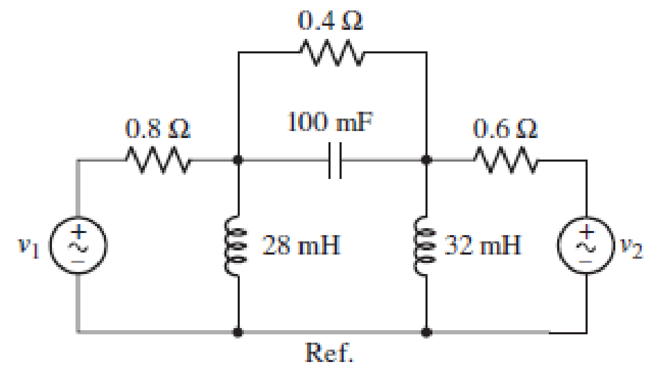
■ FIGURE 10.64
Expert Solution & Answer
Want to see the full answer?
Check out a sample textbook solution
Students have asked these similar questions
10:45 1
.III 5G
Done
Series Parallel Practice Problems
1 of 7
Series/Parallel Circuits Practice Problems
For each circuit provided, fully solve and complete the associated table.
1.
12
GOV
RS
2000
R4
3000
R3
350
R(Q)
V(v)
I(A)
P(W)
22222
300
300
35
15
200
Total
R(Q)
V(v)
I(A)
P(W)
Problem 10.007 - Nodal analysis in circuits with voltage and current sources
Use nodal analysis to find the voltage V in the circuit given below, where vs = 120 Z-15 V. Please report your answer so the
magnitude is positive and all angles are in the range of negative 180 degrees to positive 180 degrees.
V
Vs
40 Ω j20 Ω
m
www
The value of V =
6/30° A
- -j30 ΩΣ 50 Ω
° V.
10.4
Find
the
-1/4
system function for
the
following
structure.
+
-5/2
Chapter 10 Solutions
Loose Leaf for Engineering Circuit Analysis Format: Loose-leaf
Ch. 10.1 - Find the angle by which i1 lags v1 if v1 = 120...Ch. 10.2 - Determine values for A, B, C, and if 40 cos(100t ...Ch. 10.2 - Let vs = 40 cos 8000t V in the circuit of Fig....Ch. 10.3 - Prob. 4PCh. 10.3 - If the use of the passive sign convention is...Ch. 10.4 - Let = 2000 rad/s and t = 1 ms. Find the...Ch. 10.4 - Transform each of the following functions of time...Ch. 10.4 - In the circuit of Fig. 10.17, both sources operate...Ch. 10.5 - With reference to the network shown in Fig. 10.19,...Ch. 10.5 - In the frequency-domain circuit of Fig. 10.21,...
Ch. 10.5 - Determine the admittance (in rectangular form) of...Ch. 10.6 - Use nodal analysis on the circuit of Fig. 10.23 to...Ch. 10.6 - Use mesh analysis on the circuit of Fig. 10.25 to...Ch. 10.7 - If superposition is used on the circuit of Fig....Ch. 10.7 - Prob. 15PCh. 10.7 - Determine the current i through the 4 resistor of...Ch. 10.8 - Select some convenient reference value for IC in...Ch. 10 - Evaluate the following: (a) 5 sin (5t 9) at t =...Ch. 10 - (a) Express each of the following as a single...Ch. 10 - Prob. 3ECh. 10 - Prob. 4ECh. 10 - Prob. 5ECh. 10 - Calculate the first three instants in time (t 0)...Ch. 10 - (a) Determine the first two instants in time (t ...Ch. 10 - The concept of Fourier series is a powerful means...Ch. 10 - Household electrical voltages are typically quoted...Ch. 10 - Prob. 10ECh. 10 - Assuming there are no longer any transients...Ch. 10 - Calculate the power dissipated in the 2 resistor...Ch. 10 - Prob. 13ECh. 10 - Prob. 14ECh. 10 - Prob. 15ECh. 10 - Express the following complex numbers in...Ch. 10 - Prob. 17ECh. 10 - Prob. 18ECh. 10 - Evaluate the following, and express your answer in...Ch. 10 - Perform the indicated operations, and express the...Ch. 10 - Insert an appropriate complex source into the...Ch. 10 - For the circuit of Fig. 10.51, if is = 2 cos 5t A,...Ch. 10 - In the circuit depicted in Fig. 10.51, if is is...Ch. 10 - Employ a suitable complex source to determine the...Ch. 10 - Transform each of the following into phasor form:...Ch. 10 - Prob. 26ECh. 10 - Prob. 27ECh. 10 - The following complex voltages are written in a...Ch. 10 - Assuming an operating frequency of 50 Hz, compute...Ch. 10 - Prob. 30ECh. 10 - Prob. 31ECh. 10 - Prob. 32ECh. 10 - Assuming the passive sign convention and an...Ch. 10 - The circuit of Fig. 10.53 is shown represented in...Ch. 10 - (a) Obtain an expression for the equivalent...Ch. 10 - Determine the equivalent impedance of the...Ch. 10 - (a) Obtain an expression for the equivalent...Ch. 10 - Determine the equivalent admittance of the...Ch. 10 - Prob. 40ECh. 10 - Prob. 41ECh. 10 - Find V in Fig. 10.55 if the box contains (a) 3 in...Ch. 10 - Prob. 43ECh. 10 - Prob. 44ECh. 10 - Design a suitable combination of resistors,...Ch. 10 - Design a suitable combination of resistors,...Ch. 10 - For the circuit depicted in Fig. 10.58, (a) redraw...Ch. 10 - For the circuit illustrated in Fig. 10.59, (a)...Ch. 10 - Referring to the circuit of Fig. 10.59, employ...Ch. 10 - In the phasor-domain circuit represented by Fig....Ch. 10 - With regard to the two-mesh phasor-domain circuit...Ch. 10 - Employ phasor analysis techniques to obtain...Ch. 10 - Determine IB in the circuit of Fig. 10.62 if and ....Ch. 10 - Determine V2 in the circuit of Fig. 10.62 if and ....Ch. 10 - Employ phasor analysis to obtain an expression for...Ch. 10 - Determine the current ix in the circuit of Fig....Ch. 10 - Obtain an expression for each of the four...Ch. 10 - Determine the nodal voltages for the circuit of...Ch. 10 - Prob. 59ECh. 10 - Obtain an expression for each of the four mesh...Ch. 10 - Determine the individual contribution each current...Ch. 10 - Determine V1 and V2 in Fig. 10.68 if I1 = 333 mA...Ch. 10 - Prob. 63ECh. 10 - Obtain the Thvenin equivalent seen by the (2 j) ...Ch. 10 - The (2 j) impedance in the circuit of Fig. 10.69...Ch. 10 - With regard to the circuit depicted in Fig. 10.70,...Ch. 10 - Prob. 67ECh. 10 - Determine the individual contribution of each...Ch. 10 - Determine the power dissipated by the 1 resistor...Ch. 10 - The source Is in the circuit of Fig. 10.75 is...Ch. 10 - Prob. 72ECh. 10 - (a) Calculate values for IL, IR, IC, VL, VR, and...Ch. 10 - In the circuit of Fig. 10.77, (a) find values for...Ch. 10 - The voltage source Vs in Fig. 10.78 is chosen such...Ch. 10 - For the circuit shown in Fig. 10.79, (a) draw the...Ch. 10 - For the circuit shown in Fig. 10.80, (a) draw the...Ch. 10 - (a) Replace the inductor in the circuit of Fig....Ch. 10 - Design a purely passive network (containing only...
Knowledge Booster


Learn more about
Need a deep-dive on the concept behind this application? Look no further. Learn more about this topic, electrical-engineering and related others by exploring similar questions and additional content below.Similar questions
- (ACADEMIC) 8205828page%3D1 The equivalent resistance RAR (in the figure) is: A O 62. 10. BO 10. 12. b. not possible to compute without Y to Delta conversion. C. bere to search S3一4arrow_forwardQuestion 4 Giving the following tank circuit, if L= 50 mH, R=5Q and C=15µF. The approximate value of w, is 1. C 314.7 1150.36 None of the answers 1989.97arrow_forward(a) Calculate the equivalent impedance of the circuit given below, if the source voltage is v(t) = 60cos1000t (b) Calculate the source current flowing in the circuit (c) Draw the phasor diagram of the current and input voltagearrow_forward
- Q10. If the impedance of a circuit = 20 – j10n, if a voltage source is connected across this impedance, which if the following statements is correct?arrow_forward42. Find V in Fig. 10.55 if the box contains (a) 3 2 in series with 2 mH; (b) 3 2 in series with 125 µF; (c) 3 2, 2 mH, and 125 µF in series; (d) 3 2, 2 mH, and 125 µF in series, but w = 4 krad/s.arrow_forward2021.03.08 10:31 7. Compute the individual values and the total values of the voltage, the current, and the resistance of the circuit here. IT A CURRENT, RESISTANCE, VOLTAGE, V 12 I3 V; = 24v R2 R3 R1=102 R2= 200 Rg= 300arrow_forward
- Short Problem: Given a parallel RLC circuit comprised of the following element: 95.34-ohm resistor, ideal inductor with reactance of 35.57 ohms; and a capacitor with reactance of 11.63 ohms. Compute for true power in watts given an ac voltage source of 100 cis 0 volts. Note: Follow this reminder carefully. Compute to the nearest 4 decimal places. No Scientific notation. Do not round off in the middle of calculation. Use stored values. Write the numerical values only. No units in your final answer. Spaces are not allowed. Excessive number of decimals as compared to the required number of decimals may result to an incorrect answer.arrow_forwardV=225V, 20° Q R= 150, L= 125H H 7 1 C= F and 1000 f= 50Hz V R L Give the answers to one decimal place. Calculate the circuit's a) The angular frequency: rad/s b) The total impedance (give the answer as the absolute value): c) The sum of the voltages of the circuit's components R, L and C (give the answer as the absolute value):arrow_forwardProblem 10.003 - Nodal analysis in circuits with voltage sources Calculate the output voltage vo(t) of the circuit given below, where i(t) = 3 cos 4t A. Please report your answer so the magnitude is positive and all angles are in the range of negative 180 degrees to positive 180 degrees. 492 2 H 16 sin 4t V + + Vo 1/22 F 192 The output voltage of the circuit is vo(t) www 6Ω ✓✔ (Click to select) t+ sin COS °)) V.arrow_forward
- 10:55 BYV 2.00 Yo 49 (48) KB/S Two coils are A and B ar : Editing 9/7/21 10:55 AM Two coils are A and B are connected in series to a supply of 230V, 50HZ. Coil A has an inductance of 0.2H and a resistance of 20 Q, and coil B has an inductance of 0.05H and a resistance of 60 Q. Calculate the current and its phase angle relative to the supply voltage. Also determine the voltage across each coil. |arrow_forwardFor the system shown find 5, wa, percent overshoot, peak time, rise time, and settling time. R(s) E(s) 289 C(s) s(s+17)arrow_forward22. Determine the secondary current (Is) for the transformer shown in Figure 10.53a. Ip Is 80 mA -어 12:1 mA VP 120 V (a)arrow_forward
arrow_back_ios
SEE MORE QUESTIONS
arrow_forward_ios
Recommended textbooks for you
 Introductory Circuit Analysis (13th Edition)Electrical EngineeringISBN:9780133923605Author:Robert L. BoylestadPublisher:PEARSON
 Delmar's Standard Textbook Of ElectricityElectrical EngineeringISBN:9781337900348Author:Stephen L. HermanPublisher:Cengage Learning
 Programmable Logic ControllersElectrical EngineeringISBN:9780073373843Author:Frank D. PetruzellaPublisher:McGraw-Hill Education
 Fundamentals of Electric CircuitsElectrical EngineeringISBN:9780078028229Author:Charles K Alexander, Matthew SadikuPublisher:McGraw-Hill Education
 Electric Circuits. (11th Edition)Electrical EngineeringISBN:9780134746968Author:James W. Nilsson, Susan RiedelPublisher:PEARSON
 Engineering ElectromagneticsElectrical EngineeringISBN:9780078028151Author:Hayt, William H. (william Hart), Jr, BUCK, John A.Publisher:Mcgraw-hill Education,
Introductory Circuit Analysis (13th Edition)
Electrical Engineering
ISBN:9780133923605
Author:Robert L. Boylestad
Publisher:PEARSON
Delmar's Standard Textbook Of Electricity
Electrical Engineering
ISBN:9781337900348
Author:Stephen L. Herman
Publisher:Cengage Learning
Programmable Logic Controllers
Electrical Engineering
ISBN:9780073373843
Author:Frank D. Petruzella
Publisher:McGraw-Hill Education
Fundamentals of Electric Circuits
Electrical Engineering
ISBN:9780078028229
Author:Charles K Alexander, Matthew Sadiku
Publisher:McGraw-Hill Education
Electric Circuits. (11th Edition)
Electrical Engineering
ISBN:9780134746968
Author:James W. Nilsson, Susan Riedel
Publisher:PEARSON
Engineering Electromagnetics
Electrical Engineering
ISBN:9780078028151
Author:Hayt, William H. (william Hart), Jr, BUCK, John A.
Publisher:Mcgraw-hill Education,
Nodal Analysis for Circuits Explained; Author: Engineer4Free;https://www.youtube.com/watch?v=f-sbANgw4fo;License: Standard Youtube License