
Loose Leaf for Engineering Circuit Analysis Format: Loose-leaf
9th Edition
ISBN: 9781259989452
Author: Hayt
Publisher: Mcgraw Hill Publishers
expand_more
expand_more
format_list_bulleted
Concept explainers
Videos
Textbook Question
Chapter 10, Problem 42E
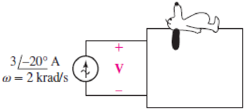
Find V in Fig. 10.55 if the box contains (a) 3 Ω in series with 2 mH; (b) 3 Ω in series with 125 μF; (c) 3 Ω, 2 mH, and 125 μF in series; (d) 3 Ω, 2 mH, and 125 μF in series, but ω = 4 krad/s.
FIGURE 10.55
Expert Solution & Answer
Want to see the full answer?
Check out a sample textbook solution
Students have asked these similar questions
10. A circuit is made up of 10 Q resistance, 12 mH
inductance and 281.5 µF capacitance in series. The
supply voltage is 100 V (constant). Calculate the
value of the current when the supply frequency is
(a) 50 Hz and (b) 150 Hz.
10. R
equivalent
AO
R,
R,
R,
300
BO
Q.4) For the power electronics circuit shown below, sketch the output voltage
waveform (Vo) and hence find its average value.
a = 80°
R - 102
40V
Vs = 200 sin cot
Vo
R = 102
Chapter 10 Solutions
Loose Leaf for Engineering Circuit Analysis Format: Loose-leaf
Ch. 10.1 - Find the angle by which i1 lags v1 if v1 = 120...Ch. 10.2 - Determine values for A, B, C, and if 40 cos(100t ...Ch. 10.2 - Let vs = 40 cos 8000t V in the circuit of Fig....Ch. 10.3 - Prob. 4PCh. 10.3 - If the use of the passive sign convention is...Ch. 10.4 - Let = 2000 rad/s and t = 1 ms. Find the...Ch. 10.4 - Transform each of the following functions of time...Ch. 10.4 - In the circuit of Fig. 10.17, both sources operate...Ch. 10.5 - With reference to the network shown in Fig. 10.19,...Ch. 10.5 - In the frequency-domain circuit of Fig. 10.21,...
Ch. 10.5 - Determine the admittance (in rectangular form) of...Ch. 10.6 - Use nodal analysis on the circuit of Fig. 10.23 to...Ch. 10.6 - Use mesh analysis on the circuit of Fig. 10.25 to...Ch. 10.7 - If superposition is used on the circuit of Fig....Ch. 10.7 - Prob. 15PCh. 10.7 - Determine the current i through the 4 resistor of...Ch. 10.8 - Select some convenient reference value for IC in...Ch. 10 - Evaluate the following: (a) 5 sin (5t 9) at t =...Ch. 10 - (a) Express each of the following as a single...Ch. 10 - Prob. 3ECh. 10 - Prob. 4ECh. 10 - Prob. 5ECh. 10 - Calculate the first three instants in time (t 0)...Ch. 10 - (a) Determine the first two instants in time (t ...Ch. 10 - The concept of Fourier series is a powerful means...Ch. 10 - Household electrical voltages are typically quoted...Ch. 10 - Prob. 10ECh. 10 - Assuming there are no longer any transients...Ch. 10 - Calculate the power dissipated in the 2 resistor...Ch. 10 - Prob. 13ECh. 10 - Prob. 14ECh. 10 - Prob. 15ECh. 10 - Express the following complex numbers in...Ch. 10 - Prob. 17ECh. 10 - Prob. 18ECh. 10 - Evaluate the following, and express your answer in...Ch. 10 - Perform the indicated operations, and express the...Ch. 10 - Insert an appropriate complex source into the...Ch. 10 - For the circuit of Fig. 10.51, if is = 2 cos 5t A,...Ch. 10 - In the circuit depicted in Fig. 10.51, if is is...Ch. 10 - Employ a suitable complex source to determine the...Ch. 10 - Transform each of the following into phasor form:...Ch. 10 - Prob. 26ECh. 10 - Prob. 27ECh. 10 - The following complex voltages are written in a...Ch. 10 - Assuming an operating frequency of 50 Hz, compute...Ch. 10 - Prob. 30ECh. 10 - Prob. 31ECh. 10 - Prob. 32ECh. 10 - Assuming the passive sign convention and an...Ch. 10 - The circuit of Fig. 10.53 is shown represented in...Ch. 10 - (a) Obtain an expression for the equivalent...Ch. 10 - Determine the equivalent impedance of the...Ch. 10 - (a) Obtain an expression for the equivalent...Ch. 10 - Determine the equivalent admittance of the...Ch. 10 - Prob. 40ECh. 10 - Prob. 41ECh. 10 - Find V in Fig. 10.55 if the box contains (a) 3 in...Ch. 10 - Prob. 43ECh. 10 - Prob. 44ECh. 10 - Design a suitable combination of resistors,...Ch. 10 - Design a suitable combination of resistors,...Ch. 10 - For the circuit depicted in Fig. 10.58, (a) redraw...Ch. 10 - For the circuit illustrated in Fig. 10.59, (a)...Ch. 10 - Referring to the circuit of Fig. 10.59, employ...Ch. 10 - In the phasor-domain circuit represented by Fig....Ch. 10 - With regard to the two-mesh phasor-domain circuit...Ch. 10 - Employ phasor analysis techniques to obtain...Ch. 10 - Determine IB in the circuit of Fig. 10.62 if and ....Ch. 10 - Determine V2 in the circuit of Fig. 10.62 if and ....Ch. 10 - Employ phasor analysis to obtain an expression for...Ch. 10 - Determine the current ix in the circuit of Fig....Ch. 10 - Obtain an expression for each of the four...Ch. 10 - Determine the nodal voltages for the circuit of...Ch. 10 - Prob. 59ECh. 10 - Obtain an expression for each of the four mesh...Ch. 10 - Determine the individual contribution each current...Ch. 10 - Determine V1 and V2 in Fig. 10.68 if I1 = 333 mA...Ch. 10 - Prob. 63ECh. 10 - Obtain the Thvenin equivalent seen by the (2 j) ...Ch. 10 - The (2 j) impedance in the circuit of Fig. 10.69...Ch. 10 - With regard to the circuit depicted in Fig. 10.70,...Ch. 10 - Prob. 67ECh. 10 - Determine the individual contribution of each...Ch. 10 - Determine the power dissipated by the 1 resistor...Ch. 10 - The source Is in the circuit of Fig. 10.75 is...Ch. 10 - Prob. 72ECh. 10 - (a) Calculate values for IL, IR, IC, VL, VR, and...Ch. 10 - In the circuit of Fig. 10.77, (a) find values for...Ch. 10 - The voltage source Vs in Fig. 10.78 is chosen such...Ch. 10 - For the circuit shown in Fig. 10.79, (a) draw the...Ch. 10 - For the circuit shown in Fig. 10.80, (a) draw the...Ch. 10 - (a) Replace the inductor in the circuit of Fig....Ch. 10 - Design a purely passive network (containing only...
Knowledge Booster


Learn more about
Need a deep-dive on the concept behind this application? Look no further. Learn more about this topic, electrical-engineering and related others by exploring similar questions and additional content below.Similar questions
- 10:55 BYV 2.00 Yo 49 (48) KB/S Two coils are A and B ar : Editing 9/7/21 10:55 AM Two coils are A and B are connected in series to a supply of 230V, 50HZ. Coil A has an inductance of 0.2H and a resistance of 20 Q, and coil B has an inductance of 0.05H and a resistance of 60 Q. Calculate the current and its phase angle relative to the supply voltage. Also determine the voltage across each coil. |arrow_forwardFor the circuit shown in Fig. 10.107, find the Norton equivalent circuit at terminals a-b. 60 Q 40 Q 3/60° A o a bo j80 N -j30 Q llarrow_forwardProblem 10.003 - Nodal analysis in circuits with voltage sources Calculate the output voltage vo(t) of the circuit given below, where i(t) = 3 cos 4t A. Please report your answer so the magnitude is positive and all angles are in the range of negative 180 degrees to positive 180 degrees. 492 2 H 16 sin 4t V + + Vo 1/22 F 192 The output voltage of the circuit is vo(t) www 6Ω ✓✔ (Click to select) t+ sin COS °)) V.arrow_forward
- 42. Find V in Fig. 10.55 if the box contains (a) 3 2 in series with 2 mH; (b) 3 2 in series with 125 µF; (c) 3 2, 2 mH, and 125 µF in series; (d) 3 2, 2 mH, and 125 µF in series, but w = 4 krad/s.arrow_forward10.) Find Req 10 N 10 Ω Rea 10 Narrow_forwardDetermine the Thevenin equivalent of the circuit in Fig. 10. 27 as seen from terminals a-b. 82 j42 ll ww o a -j22 5/0° A 0.2V 42arrow_forward
- 15 Find i for the circuit shown in Fig. 10-19. HH 0.001 μF 10 cos 106t V +21 500 Ω Fig. 10-19 See Prob. 5. 12+ 10 cos 2 x 10⁶arrow_forwardCalculate current of inductor and voltage of capacitor in transient state after turning on the switch in the circuit of Fig. 10.25. Assume: R=5Ω, C=100μF, L=1H, e1(t)=10V, e2(t)=10V.arrow_forward16 0 t = 0' 4 V 0.5 H 312.5 рF Vs(t) = 4 V Constant voltage source Ve(t) = Vo(t) Voltage across capacitor ic(t) Current flowing through the сараcitor inductance voltage across VL(t) ilt) inductance Inductance current VR(t) Voltage across resistor İR(t) Current flowing through resistor Vc(0) 3 V Capacitor voltage at time t=0 After the switch has been open long enough, it is closed at t=0. Which of the following is the Laplace transform of the current ic(t)? ir(t)? vr(t)=? Vc(t)=?arrow_forward
- ITORS 3 μF 6 μF 0.2 μF HE 7 μF 24 CT SECTION 10.13 Capacitors in Series and Parallel 44. Find the total capacitance C, between points a and b of the circuits of Fig. 10.104. 60 pF O a 30 pF CT b 20 pF (b) # 10 pFarrow_forwardFigure 1090 For Prob. 1047. 10.48 Find i, in the circuit in Fig. 10.91 y superposition. A 10.: in the 50 cos 20007 V 0s(2t - 60°) V 2 sin 40001 A 10.5 Figure 1091 oarrow_forward3. Referring to the circuit shown below. If v(t) is 120 cos (1000t-30°) V, determine the following: (a) Inductor current (b) The voltage between terminals a and b, Vab a v(t) 302 -WW- 6Ω 8mH Note: Express your final answer in polar form. www 4Ω b 125μFarrow_forward
arrow_back_ios
SEE MORE QUESTIONS
arrow_forward_ios
Recommended textbooks for you
 Introductory Circuit Analysis (13th Edition)Electrical EngineeringISBN:9780133923605Author:Robert L. BoylestadPublisher:PEARSON
 Delmar's Standard Textbook Of ElectricityElectrical EngineeringISBN:9781337900348Author:Stephen L. HermanPublisher:Cengage Learning
 Programmable Logic ControllersElectrical EngineeringISBN:9780073373843Author:Frank D. PetruzellaPublisher:McGraw-Hill Education
 Fundamentals of Electric CircuitsElectrical EngineeringISBN:9780078028229Author:Charles K Alexander, Matthew SadikuPublisher:McGraw-Hill Education
 Electric Circuits. (11th Edition)Electrical EngineeringISBN:9780134746968Author:James W. Nilsson, Susan RiedelPublisher:PEARSON
 Engineering ElectromagneticsElectrical EngineeringISBN:9780078028151Author:Hayt, William H. (william Hart), Jr, BUCK, John A.Publisher:Mcgraw-hill Education,
Introductory Circuit Analysis (13th Edition)
Electrical Engineering
ISBN:9780133923605
Author:Robert L. Boylestad
Publisher:PEARSON
Delmar's Standard Textbook Of Electricity
Electrical Engineering
ISBN:9781337900348
Author:Stephen L. Herman
Publisher:Cengage Learning
Programmable Logic Controllers
Electrical Engineering
ISBN:9780073373843
Author:Frank D. Petruzella
Publisher:McGraw-Hill Education
Fundamentals of Electric Circuits
Electrical Engineering
ISBN:9780078028229
Author:Charles K Alexander, Matthew Sadiku
Publisher:McGraw-Hill Education
Electric Circuits. (11th Edition)
Electrical Engineering
ISBN:9780134746968
Author:James W. Nilsson, Susan Riedel
Publisher:PEARSON
Engineering Electromagnetics
Electrical Engineering
ISBN:9780078028151
Author:Hayt, William H. (william Hart), Jr, BUCK, John A.
Publisher:Mcgraw-hill Education,
Current Divider Rule; Author: Neso Academy;https://www.youtube.com/watch?v=hRU1mKWUehY;License: Standard YouTube License, CC-BY