
Loose Leaf for Engineering Circuit Analysis Format: Loose-leaf
9th Edition
ISBN: 9781259989452
Author: Hayt
Publisher: Mcgraw Hill Publishers
expand_more
expand_more
format_list_bulleted
Videos
Textbook Question
Chapter 10, Problem 76E
For the circuit shown in Fig. 10.79, (a) draw the phasor representation of the circuit; (b) determine the Thévenin equivalent seen by the capacitor, and use it to calculate vC(t). (c) Determine the current flowing out of the positive reference terminal of the voltage source. (d) Verify your solution with an appropriate LTspice simulation.
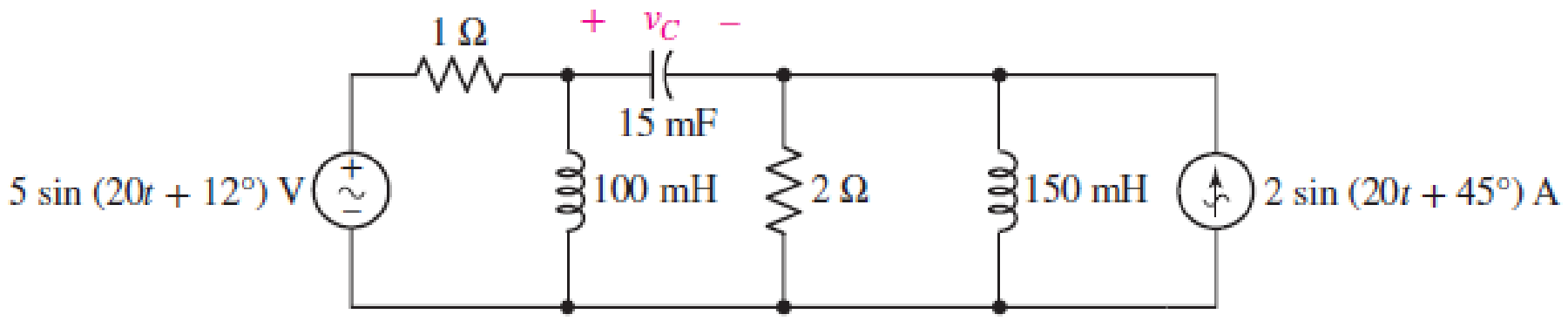
■ FIGURE 10.79
Expert Solution & Answer
Want to see the full answer?
Check out a sample textbook solution
Students have asked these similar questions
4. In a linear circuit, the voltage source is
Vs = 12 sin(10°t + 24') V
(a) What is the angular frequency of the voltage?
(b) What is the frequency of the source?
(c) Find the period of the voltage.
(d) Find the Vrms value.
Based on the following circuit, obtain the following:A) Equivalent capacitance of the circuit.B) Charging time of the capacitor array between points A and B. Useequivalent capacitance.
An R–L–C series circuit has a maximum cur
rent of 2 mA flowing in it when the frequency
of the 0.1 V supply is 4 kHz. The Q-factor
of the circuit under these conditions is 90.
Determine (a) the voltage across the capaci
tor and (b) the values of the circuit resistance,
inductance and capacitance.
Calculate the inductance of a coil which must
be connected in series with a 4000 pF capacitor
to give a resonant frequency of 200 kHz. If the
coil has a resistance of 12 ohm , determine the
circuit Q-factor.
Chapter 10 Solutions
Loose Leaf for Engineering Circuit Analysis Format: Loose-leaf
Ch. 10.1 - Find the angle by which i1 lags v1 if v1 = 120...Ch. 10.2 - Determine values for A, B, C, and if 40 cos(100t ...Ch. 10.2 - Let vs = 40 cos 8000t V in the circuit of Fig....Ch. 10.3 - Prob. 4PCh. 10.3 - If the use of the passive sign convention is...Ch. 10.4 - Let = 2000 rad/s and t = 1 ms. Find the...Ch. 10.4 - Transform each of the following functions of time...Ch. 10.4 - In the circuit of Fig. 10.17, both sources operate...Ch. 10.5 - With reference to the network shown in Fig. 10.19,...Ch. 10.5 - In the frequency-domain circuit of Fig. 10.21,...
Ch. 10.5 - Determine the admittance (in rectangular form) of...Ch. 10.6 - Use nodal analysis on the circuit of Fig. 10.23 to...Ch. 10.6 - Use mesh analysis on the circuit of Fig. 10.25 to...Ch. 10.7 - If superposition is used on the circuit of Fig....Ch. 10.7 - Prob. 15PCh. 10.7 - Determine the current i through the 4 resistor of...Ch. 10.8 - Select some convenient reference value for IC in...Ch. 10 - Evaluate the following: (a) 5 sin (5t 9) at t =...Ch. 10 - (a) Express each of the following as a single...Ch. 10 - Prob. 3ECh. 10 - Prob. 4ECh. 10 - Prob. 5ECh. 10 - Calculate the first three instants in time (t 0)...Ch. 10 - (a) Determine the first two instants in time (t ...Ch. 10 - The concept of Fourier series is a powerful means...Ch. 10 - Household electrical voltages are typically quoted...Ch. 10 - Prob. 10ECh. 10 - Assuming there are no longer any transients...Ch. 10 - Calculate the power dissipated in the 2 resistor...Ch. 10 - Prob. 13ECh. 10 - Prob. 14ECh. 10 - Prob. 15ECh. 10 - Express the following complex numbers in...Ch. 10 - Prob. 17ECh. 10 - Prob. 18ECh. 10 - Evaluate the following, and express your answer in...Ch. 10 - Perform the indicated operations, and express the...Ch. 10 - Insert an appropriate complex source into the...Ch. 10 - For the circuit of Fig. 10.51, if is = 2 cos 5t A,...Ch. 10 - In the circuit depicted in Fig. 10.51, if is is...Ch. 10 - Employ a suitable complex source to determine the...Ch. 10 - Transform each of the following into phasor form:...Ch. 10 - Prob. 26ECh. 10 - Prob. 27ECh. 10 - The following complex voltages are written in a...Ch. 10 - Assuming an operating frequency of 50 Hz, compute...Ch. 10 - Prob. 30ECh. 10 - Prob. 31ECh. 10 - Prob. 32ECh. 10 - Assuming the passive sign convention and an...Ch. 10 - The circuit of Fig. 10.53 is shown represented in...Ch. 10 - (a) Obtain an expression for the equivalent...Ch. 10 - Determine the equivalent impedance of the...Ch. 10 - (a) Obtain an expression for the equivalent...Ch. 10 - Determine the equivalent admittance of the...Ch. 10 - Prob. 40ECh. 10 - Prob. 41ECh. 10 - Find V in Fig. 10.55 if the box contains (a) 3 in...Ch. 10 - Prob. 43ECh. 10 - Prob. 44ECh. 10 - Design a suitable combination of resistors,...Ch. 10 - Design a suitable combination of resistors,...Ch. 10 - For the circuit depicted in Fig. 10.58, (a) redraw...Ch. 10 - For the circuit illustrated in Fig. 10.59, (a)...Ch. 10 - Referring to the circuit of Fig. 10.59, employ...Ch. 10 - In the phasor-domain circuit represented by Fig....Ch. 10 - With regard to the two-mesh phasor-domain circuit...Ch. 10 - Employ phasor analysis techniques to obtain...Ch. 10 - Determine IB in the circuit of Fig. 10.62 if and ....Ch. 10 - Determine V2 in the circuit of Fig. 10.62 if and ....Ch. 10 - Employ phasor analysis to obtain an expression for...Ch. 10 - Determine the current ix in the circuit of Fig....Ch. 10 - Obtain an expression for each of the four...Ch. 10 - Determine the nodal voltages for the circuit of...Ch. 10 - Prob. 59ECh. 10 - Obtain an expression for each of the four mesh...Ch. 10 - Determine the individual contribution each current...Ch. 10 - Determine V1 and V2 in Fig. 10.68 if I1 = 333 mA...Ch. 10 - Prob. 63ECh. 10 - Obtain the Thvenin equivalent seen by the (2 j) ...Ch. 10 - The (2 j) impedance in the circuit of Fig. 10.69...Ch. 10 - With regard to the circuit depicted in Fig. 10.70,...Ch. 10 - Prob. 67ECh. 10 - Determine the individual contribution of each...Ch. 10 - Determine the power dissipated by the 1 resistor...Ch. 10 - The source Is in the circuit of Fig. 10.75 is...Ch. 10 - Prob. 72ECh. 10 - (a) Calculate values for IL, IR, IC, VL, VR, and...Ch. 10 - In the circuit of Fig. 10.77, (a) find values for...Ch. 10 - The voltage source Vs in Fig. 10.78 is chosen such...Ch. 10 - For the circuit shown in Fig. 10.79, (a) draw the...Ch. 10 - For the circuit shown in Fig. 10.80, (a) draw the...Ch. 10 - (a) Replace the inductor in the circuit of Fig....Ch. 10 - Design a purely passive network (containing only...
Knowledge Booster


Learn more about
Need a deep-dive on the concept behind this application? Look no further. Learn more about this topic, electrical-engineering and related others by exploring similar questions and additional content below.Similar questions
- Given the circuit below a. find the MAGNITUDE of the current through the capacitor (in mA with 2 decimal places) b. find the MAGNITUDE of the current through the inductor (in mA with 2 decimal places) c. find the MAGNITUDE of the total real power (in WATTS with 2 decimal places)arrow_forward%3D 5. In Figure, after switch S is closed at time t 0, the emf of the source is automatically adjusted to maintain a constant current Constant i through S. Current source a) ts)Find the current through the inductor as a function of time. b) At what time is the current through the resistor equal to the current through the inductor? itis di. dis し、arrow_forward10.29 The capacitor is initially charged to 6V with the polarity shown 4.7 k + 40 V "C a) Write the expression for the voltage vC after the switch is closed. b) Write the expression for the current iC after the switch if closed. C) Plot the results of a) and b)arrow_forward
- 1) Determine the Capacitance value to calculate the time constant of the circuit.2) Determine the time constant of the circuit for the capacities you have determined.3) For the capacity value, calculate the estimated time to come to the final state.4) Plot capacitor current and voltage graphs and show if it works in harmony with the time constant you calculated.NOTE: if you want you can use falstad online circuit simulator.arrow_forwardA 50 and 100-microfarad capacitors are connected in series and connected across a 100sin(ωt +30°) voltage. Write the equation of the current. (Assume f=60Hz)arrow_forwardFind the equivalent impedance Zeq seen by the source when Vs = 4 cos (2t) v, C = 1 F, R = 3 2 and L = 0.5 H. (Give angles in degrees and round final answers to two decimal places.) Calculate the voltage across each component - capacitor, resistor and inductor. (Give angles in degrees and round final answers to two decimal places.) Vs R The equivalent impedance seen by the source is Q. The voltage across the capacitor is The voltage across the resistor is The voltage across the inductor is at an angle of at an angle of at an angle of + V. V. V. Q= at an angle ofarrow_forward
- 2 A voltage e(t) = 100sin 314t is applied to a series circuit consisting of 10ohms resistance, 0.0318H inductance and a capacitor of 63.6uF. Calculate a)expression for i(t), b)phase angle between voltage and current, c) power factor and active power consumed, d) peak value of the pulsating energy, e) draw the diagrams and circuit.arrow_forwardFundamentals of Electrical Engineering 2020/2021 Dr. Yaseen H. Tahir xample: (example 15-3, page 388, David) (H. W.) A1 MF capacitance is to be constructed from rolled-up sheets of aluminum foil separated by a layer of paper 0.1l mm thick. Calculate the required area for each sheet of foil if the relative permittivity of the paper is 6.arrow_forward99100 "By practice, an ideal capacitor models a practical capacitor quite accurately." True False Phasor relationship of the voltage and current of an ideal capacitor is out of phase. True Falsearrow_forward
- A. 25 Hz B. 60 Hz C. 75 Hz D. 100 Hz 1. A coil of 10 Q resistance and 0.1 H inductance is connected in parallel with a capacitor of unknown capacitance. If the total impedance of the combination is 100 n, determine the value of the capacitanc?. A. 50 µF (B) 100 µF C. 150 µF D. 200 µF REE - March 1998arrow_forwardShort Problem: Given a parallel RLC circuit comprised of the following element: 63.27-ohm resistor, ideal inductor with reactance of 63.75 ohms; and a capacitor with reactance of 6.25 ohms. Compute for reactive power in VArs given an ac voltage source of 100 cis 0 volts. Give only the absolute value. Note: Follow this reminder carefully. Compute to the nearest 4 decimal places. No Scientific notation. Do not round off in the middle of calculation. Use stored values. Write the numerical values only. No units in your final answer. Spaces are not allowed. Excessive number of decimals as compared to the required number of decimals may result to an incorrect answer.arrow_forwardCalculate the equivalent capacitance, the equivalent charge, V1234, V67, and Q6.arrow_forward
arrow_back_ios
SEE MORE QUESTIONS
arrow_forward_ios
Recommended textbooks for you
 Introductory Circuit Analysis (13th Edition)Electrical EngineeringISBN:9780133923605Author:Robert L. BoylestadPublisher:PEARSON
 Delmar's Standard Textbook Of ElectricityElectrical EngineeringISBN:9781337900348Author:Stephen L. HermanPublisher:Cengage Learning
 Programmable Logic ControllersElectrical EngineeringISBN:9780073373843Author:Frank D. PetruzellaPublisher:McGraw-Hill Education
 Fundamentals of Electric CircuitsElectrical EngineeringISBN:9780078028229Author:Charles K Alexander, Matthew SadikuPublisher:McGraw-Hill Education
 Electric Circuits. (11th Edition)Electrical EngineeringISBN:9780134746968Author:James W. Nilsson, Susan RiedelPublisher:PEARSON
 Engineering ElectromagneticsElectrical EngineeringISBN:9780078028151Author:Hayt, William H. (william Hart), Jr, BUCK, John A.Publisher:Mcgraw-hill Education,
Introductory Circuit Analysis (13th Edition)
Electrical Engineering
ISBN:9780133923605
Author:Robert L. Boylestad
Publisher:PEARSON
Delmar's Standard Textbook Of Electricity
Electrical Engineering
ISBN:9781337900348
Author:Stephen L. Herman
Publisher:Cengage Learning
Programmable Logic Controllers
Electrical Engineering
ISBN:9780073373843
Author:Frank D. Petruzella
Publisher:McGraw-Hill Education
Fundamentals of Electric Circuits
Electrical Engineering
ISBN:9780078028229
Author:Charles K Alexander, Matthew Sadiku
Publisher:McGraw-Hill Education
Electric Circuits. (11th Edition)
Electrical Engineering
ISBN:9780134746968
Author:James W. Nilsson, Susan Riedel
Publisher:PEARSON
Engineering Electromagnetics
Electrical Engineering
ISBN:9780078028151
Author:Hayt, William H. (william Hart), Jr, BUCK, John A.
Publisher:Mcgraw-hill Education,
Routh Hurwitz Stability Criterion Basic Worked Example; Author: The Complete Guide to Everything;https://www.youtube.com/watch?v=CzzsR5FT-8U;License: Standard Youtube License