
Loose Leaf for Engineering Circuit Analysis Format: Loose-leaf
9th Edition
ISBN: 9781259989452
Author: Hayt
Publisher: Mcgraw Hill Publishers
expand_more
expand_more
format_list_bulleted
Videos
Textbook Question
Chapter 10.8, Problem 17P
Select some convenient reference value for IC in the circuit of Fig. 10.44; draw a phasor diagram showing VR, V2, V1, and Vs; and measure the ratio of the lengths of (a) Vs to V1; (b) V1 to V2; (c) Vs to VR.
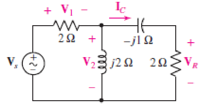
■ FIGURE 10.44
Expert Solution & Answer
Want to see the full answer?
Check out a sample textbook solution
Students have asked these similar questions
(ACADEMIC)
8205828page%3D1
The equivalent resistance RAR (in the figure) is:
A O
62.
10.
BO
10.
12.
b.
not possible to compute without Y to Delta conversion.
C.
bere to search
S3一4
A series circuit contains a resistor and an inductor as shown in Figure below. Determine a differential equation for the current i(f) if the resistance is R, the inductance is L, and the impressed voltage is E(t).
Then determine the current i(t), with R = 4 N, L = 2 h, E (t) = cos(3t) using the ordinary variation of parameters method. Later Solve the same determined ODE using the Laplace transform (determine i(t) using Laplace transform) and compare the two Methods. for initial conditions, i(0) = 0
Given a parallel RLC circuit comprised of the following element: 99.3-ohm resistor, ideal inductor with reactance of 66.76 ohms; and a capacitor with reactance of 19.7 ohms. Compute for true power in watts given an ac voltage source of 100 cis 0 volts.
Compute to the nearest 4 decimal places. No Scientific notation. Do not round off in the middle of calculation.
Chapter 10 Solutions
Loose Leaf for Engineering Circuit Analysis Format: Loose-leaf
Ch. 10.1 - Find the angle by which i1 lags v1 if v1 = 120...Ch. 10.2 - Determine values for A, B, C, and if 40 cos(100t ...Ch. 10.2 - Let vs = 40 cos 8000t V in the circuit of Fig....Ch. 10.3 - Prob. 4PCh. 10.3 - If the use of the passive sign convention is...Ch. 10.4 - Let = 2000 rad/s and t = 1 ms. Find the...Ch. 10.4 - Transform each of the following functions of time...Ch. 10.4 - In the circuit of Fig. 10.17, both sources operate...Ch. 10.5 - With reference to the network shown in Fig. 10.19,...Ch. 10.5 - In the frequency-domain circuit of Fig. 10.21,...
Ch. 10.5 - Determine the admittance (in rectangular form) of...Ch. 10.6 - Use nodal analysis on the circuit of Fig. 10.23 to...Ch. 10.6 - Use mesh analysis on the circuit of Fig. 10.25 to...Ch. 10.7 - If superposition is used on the circuit of Fig....Ch. 10.7 - Prob. 15PCh. 10.7 - Determine the current i through the 4 resistor of...Ch. 10.8 - Select some convenient reference value for IC in...Ch. 10 - Evaluate the following: (a) 5 sin (5t 9) at t =...Ch. 10 - (a) Express each of the following as a single...Ch. 10 - Prob. 3ECh. 10 - Prob. 4ECh. 10 - Prob. 5ECh. 10 - Calculate the first three instants in time (t 0)...Ch. 10 - (a) Determine the first two instants in time (t ...Ch. 10 - The concept of Fourier series is a powerful means...Ch. 10 - Household electrical voltages are typically quoted...Ch. 10 - Prob. 10ECh. 10 - Assuming there are no longer any transients...Ch. 10 - Calculate the power dissipated in the 2 resistor...Ch. 10 - Prob. 13ECh. 10 - Prob. 14ECh. 10 - Prob. 15ECh. 10 - Express the following complex numbers in...Ch. 10 - Prob. 17ECh. 10 - Prob. 18ECh. 10 - Evaluate the following, and express your answer in...Ch. 10 - Perform the indicated operations, and express the...Ch. 10 - Insert an appropriate complex source into the...Ch. 10 - For the circuit of Fig. 10.51, if is = 2 cos 5t A,...Ch. 10 - In the circuit depicted in Fig. 10.51, if is is...Ch. 10 - Employ a suitable complex source to determine the...Ch. 10 - Transform each of the following into phasor form:...Ch. 10 - Prob. 26ECh. 10 - Prob. 27ECh. 10 - The following complex voltages are written in a...Ch. 10 - Assuming an operating frequency of 50 Hz, compute...Ch. 10 - Prob. 30ECh. 10 - Prob. 31ECh. 10 - Prob. 32ECh. 10 - Assuming the passive sign convention and an...Ch. 10 - The circuit of Fig. 10.53 is shown represented in...Ch. 10 - (a) Obtain an expression for the equivalent...Ch. 10 - Determine the equivalent impedance of the...Ch. 10 - (a) Obtain an expression for the equivalent...Ch. 10 - Determine the equivalent admittance of the...Ch. 10 - Prob. 40ECh. 10 - Prob. 41ECh. 10 - Find V in Fig. 10.55 if the box contains (a) 3 in...Ch. 10 - Prob. 43ECh. 10 - Prob. 44ECh. 10 - Design a suitable combination of resistors,...Ch. 10 - Design a suitable combination of resistors,...Ch. 10 - For the circuit depicted in Fig. 10.58, (a) redraw...Ch. 10 - For the circuit illustrated in Fig. 10.59, (a)...Ch. 10 - Referring to the circuit of Fig. 10.59, employ...Ch. 10 - In the phasor-domain circuit represented by Fig....Ch. 10 - With regard to the two-mesh phasor-domain circuit...Ch. 10 - Employ phasor analysis techniques to obtain...Ch. 10 - Determine IB in the circuit of Fig. 10.62 if and ....Ch. 10 - Determine V2 in the circuit of Fig. 10.62 if and ....Ch. 10 - Employ phasor analysis to obtain an expression for...Ch. 10 - Determine the current ix in the circuit of Fig....Ch. 10 - Obtain an expression for each of the four...Ch. 10 - Determine the nodal voltages for the circuit of...Ch. 10 - Prob. 59ECh. 10 - Obtain an expression for each of the four mesh...Ch. 10 - Determine the individual contribution each current...Ch. 10 - Determine V1 and V2 in Fig. 10.68 if I1 = 333 mA...Ch. 10 - Prob. 63ECh. 10 - Obtain the Thvenin equivalent seen by the (2 j) ...Ch. 10 - The (2 j) impedance in the circuit of Fig. 10.69...Ch. 10 - With regard to the circuit depicted in Fig. 10.70,...Ch. 10 - Prob. 67ECh. 10 - Determine the individual contribution of each...Ch. 10 - Determine the power dissipated by the 1 resistor...Ch. 10 - The source Is in the circuit of Fig. 10.75 is...Ch. 10 - Prob. 72ECh. 10 - (a) Calculate values for IL, IR, IC, VL, VR, and...Ch. 10 - In the circuit of Fig. 10.77, (a) find values for...Ch. 10 - The voltage source Vs in Fig. 10.78 is chosen such...Ch. 10 - For the circuit shown in Fig. 10.79, (a) draw the...Ch. 10 - For the circuit shown in Fig. 10.80, (a) draw the...Ch. 10 - (a) Replace the inductor in the circuit of Fig....Ch. 10 - Design a purely passive network (containing only...
Knowledge Booster


Learn more about
Need a deep-dive on the concept behind this application? Look no further. Learn more about this topic, electrical-engineering and related others by exploring similar questions and additional content below.Similar questions
- A series circuit contains a resistor and an inductor as shown in Figure below. Determine a differential equation for the current i(f) if the resistance is R, the inductance is L, and the impressed voltage is E(t). Then determine the current i(t), with R = 4 N, L = 2 h, E (t) = cos(3t) using the ordinary variation of parameters method. Later Solve the same determined ODE using the Laplace transform (determine i(t) using Laplace transform) and compare the two Methods. for initial conditions, i(0) = 0 Finally illustrate the Laplace transform solution steps to ODES with a diagram that summarizes the steps you used to carry out your solution.arrow_forwardQ.5) For the following system shown below, determine the characteristic equation, the rise time, settling time, and also calculate the value of K and j so that the peak time is 1 sec, maximum overshoot is 0.2 when a unit step input is applied. K R(s) C(s) s2 + s 1+js Hint: - The settling time 4 :47 t = Swn %3Darrow_forwardVOLTE ll O ON100% 10:48 + IMG_4550.jpg For the circuit shown, it is required to design a circuit with minimum losses. The value of n (the turns ratio) that maximizes the transferred power to the secondary coil is. (ABET assessment of outcome 2) 4000 2 1:n 120/0°V rms 10 Ω 0.1 O 0.0025 20 400 0.05 None of the above ellarrow_forward
- Q.5) For the following system shown below, determine the characteristic equation, the rise time, settling time, and also calculate the value of K and j so that the peak time is 1 sec, maximum overshoot is 0.2 when a unit step input is applied. K C(s) R(s) s2 + s 1+js Hint: The settling time 4 %3D ts = 4T 8wnarrow_forwardPOWER SİSTEMS high voltage technique it is possible to measure pulsed (AND ANSWER THE SAME QUESTION FOR AC AND DC ) high voltages with the help of two spheres of equal radius placed on the same axis. In which case the approximate impulse,AC AND DC voltage value that can be measured with such a system with diameters of 500 mm and known spacing between them is 2.5 cm, is given correctly. (Ambient conditions are neglected and take Ed = 30 kV / cm2 k = 0.9) a) 68,65114 kV b) 81.30081 kv c) 97,08737 kv d) 65,35947 kv e) 57.48835 kv f) 46.21612 kv PLEASE ANSWER THE SAME QUESTION FOR DC HİGH VOLTAGE AND AC HİGH VOLTAGE WHAT THE DIFFERENCE BETWEEN THEMarrow_forwardQ.5) For the following system shown below, determine the characteristic equation, the rise time, settling time, and also calculate the value of K and j so that the peak time is 1 sec, maximum overshoot is 0.2 when a unit step input is applied. K R(s) C(s) s2 + s 1+js Hint: - The settling time 4 4T ts = %3D Swnarrow_forward
- Given a parallel RLC circuit comprised of the following element: 63.92-ohm resistor, ideal inductor with reactance of 46.65 ohms; and a capacitor with reactance of 8.65 ohms. Compute for true power in watts given an ac voltage source of 100 cis 0 volts. Compute to the nearest 4 decimal places. No Scientific notation. Do not round off in the middle of calculation. Use stored values.arrow_forwardB- An ac bridge has the following constants; arm AB, a resistance of 3000 £2 in series with an inductance of 0.4H; BC, a resistance of 450002 in series with an inductance of 0.6H; CD, pure resistance 35900; DA, pure resistance 241002. An oscillator maintains an emf of 15V (rms) at w-2nf-10K radians per second between terminals A and C. the detector is a telephone handset with impedance 1258+j3600 2 at this frequency. Find the current that flows in the detector for the above condition.arrow_forwardhigh voltage technique choose the correct answer It is possible to measure pulsed high voltages with the help of two spheres of equal radius placed on the same axis. In which case the approximate impulse voltage value that can be measured with such a system with diameters of 500 mm and known spacing between them is 2.5 cm, is given correctly. (Ambient conditions are neglected and take Ed = 30 kV / cm2 k = 0.9) a) 68,65114 kV b) 81.30081 kv c) 97,08737 kv d) 65,35947 kv e) 57.48835 kv f) 46.21612 kvarrow_forward
- Short Problem: Given a parallel RLC circuit comprised of the following element: 63.27-ohm resistor, ideal inductor with reactance of 63.75 ohms; and a capacitor with reactance of 6.25 ohms. Compute for reactive power in VArs given an ac voltage source of 100 cis 0 volts. Give only the absolute value. Note: Follow this reminder carefully. Compute to the nearest 4 decimal places. No Scientific notation. Do not round off in the middle of calculation. Use stored values. Write the numerical values only. No units in your final answer. Spaces are not allowed. Excessive number of decimals as compared to the required number of decimals may result to an incorrect answer.arrow_forwardSolve no.10 and show solutions. (Situation no.05 image below)arrow_forwardVc = 12V() - e-t/100us): I 10.23 Given the voltage a) What is the time constant? b) What is the voltage at t=50us? c) What is the voltage at t=1ms?arrow_forward
arrow_back_ios
SEE MORE QUESTIONS
arrow_forward_ios
Recommended textbooks for you
 Introductory Circuit Analysis (13th Edition)Electrical EngineeringISBN:9780133923605Author:Robert L. BoylestadPublisher:PEARSON
 Delmar's Standard Textbook Of ElectricityElectrical EngineeringISBN:9781337900348Author:Stephen L. HermanPublisher:Cengage Learning
 Programmable Logic ControllersElectrical EngineeringISBN:9780073373843Author:Frank D. PetruzellaPublisher:McGraw-Hill Education
 Fundamentals of Electric CircuitsElectrical EngineeringISBN:9780078028229Author:Charles K Alexander, Matthew SadikuPublisher:McGraw-Hill Education
 Electric Circuits. (11th Edition)Electrical EngineeringISBN:9780134746968Author:James W. Nilsson, Susan RiedelPublisher:PEARSON
 Engineering ElectromagneticsElectrical EngineeringISBN:9780078028151Author:Hayt, William H. (william Hart), Jr, BUCK, John A.Publisher:Mcgraw-hill Education,
Introductory Circuit Analysis (13th Edition)
Electrical Engineering
ISBN:9780133923605
Author:Robert L. Boylestad
Publisher:PEARSON
Delmar's Standard Textbook Of Electricity
Electrical Engineering
ISBN:9781337900348
Author:Stephen L. Herman
Publisher:Cengage Learning
Programmable Logic Controllers
Electrical Engineering
ISBN:9780073373843
Author:Frank D. Petruzella
Publisher:McGraw-Hill Education
Fundamentals of Electric Circuits
Electrical Engineering
ISBN:9780078028229
Author:Charles K Alexander, Matthew Sadiku
Publisher:McGraw-Hill Education
Electric Circuits. (11th Edition)
Electrical Engineering
ISBN:9780134746968
Author:James W. Nilsson, Susan Riedel
Publisher:PEARSON
Engineering Electromagnetics
Electrical Engineering
ISBN:9780078028151
Author:Hayt, William H. (william Hart), Jr, BUCK, John A.
Publisher:Mcgraw-hill Education,
Nyquist 1 - what is a Nyquist diagram?; Author: John Rossiter;https://www.youtube.com/watch?v=mgIvOk9JGKY;License: Standard Youtube License