
Shigley's Mechanical Engineering Design (McGraw-Hill Series in Mechanical Engineering)
10th Edition
ISBN: 9780073398204
Author: Richard G Budynas, Keith J Nisbett
Publisher: McGraw-Hill Education
expand_more
expand_more
format_list_bulleted
Concept explainers
Videos
Textbook Question
thumb_up100%
Chapter 13, Problem 17P
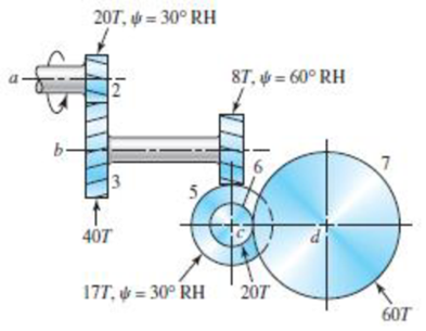
Shaft a in the figure rotates at 600 rev/min in the direction shown. Find the speed and direction of rotation of shaft d.
Problem 13-17
Expert Solution & Answer

Trending nowThis is a popular solution!

Students have asked these similar questions
13-32
The 247 6-pitch 20° pinion 2 shown in the figure rotates clockwise at 1000 rev/min and is driven at a power of 25 hp. Gears 4, 5, and 6 have 24, 36, and 144 teeth, respectively. What torque can arm 3 deliver to its output shaft? Draw free-body diagrams of the arm and of each gear and show all forces that act upon them.
The figure shows a 16T 20' straight bevel pinion driving a 32T gear, and the location of the bearing
centerlines. Pinion shaft a receives 2.5 hp at 243 rev/min. Determine the bearing reactions at A and B
if A is to take both radial and thrust loads.
Question 1:
The figure shows a 16T 20° straight bevel pinion driving a 32T gear, and the location of the bearing
centerlines. Pinion shaft a receives 2.5 hp at 248 rev/min. Determine the bearing reactions at A and
B if A is to take both radial and thrust loads.
On-Screen Keyboard
Esc
1
3.
4 5
6.
Chapter 13 Solutions
Shigley's Mechanical Engineering Design (McGraw-Hill Series in Mechanical Engineering)
Ch. 13 - A 17-tooth spur pinion has a diametral pitch of 8...Ch. 13 - A 15-tooth spur pinion has a module of 3 mm and...Ch. 13 - A spur gearset has a module of 6 mm and a velocity...Ch. 13 - A 21-tooth spur pinion mates with a 28-tooth gear....Ch. 13 - A 20 straight-tooth bevel pinion having 14 teeth...Ch. 13 - A parallel helical gearset uses a 20-tooth pinion...Ch. 13 - A parallel helical gearset consists of a 19-tooth...Ch. 13 - To avoid the problem of interference in a pair of...Ch. 13 - Prob. 9PCh. 13 - Prob. 10P
Ch. 13 - Prob. 11PCh. 13 - Prob. 12PCh. 13 - Prob. 13PCh. 13 - Prob. 14PCh. 13 - A parallel-shaft gearset consists of an 18-tooth...Ch. 13 - The double-reduction helical gearset shown in the...Ch. 13 - Shaft a in the figure rotates at 600 rev/min in...Ch. 13 - The mechanism train shown consists of an...Ch. 13 - The figure shows a gear train consisting of a pair...Ch. 13 - A compound reverted gear trains are to be designed...Ch. 13 - Prob. 21PCh. 13 - Prob. 22PCh. 13 - Prob. 23PCh. 13 - A gearbox is to be designed with a compound...Ch. 13 - The tooth numbers for the automotive differential...Ch. 13 - Prob. 26PCh. 13 - In the reverted planetary train illustrated, find...Ch. 13 - Prob. 28PCh. 13 - Tooth numbers for the gear train shown in the...Ch. 13 - The tooth numbers for the gear train illustrated...Ch. 13 - Shaft a in the figure has a power input of 75 kW...Ch. 13 - The 24T 6-pitch 20 pinion 2 shown in the figure...Ch. 13 - The gears shown in the figure have a module of 12...Ch. 13 - The figure shows a pair of shaft-mounted spur...Ch. 13 - Prob. 35PCh. 13 - Prob. 36PCh. 13 - A speed-reducer gearbox containing a compound...Ch. 13 - For the countershaft in Prob. 3-72, p. 152, assume...Ch. 13 - Prob. 39PCh. 13 - Prob. 40PCh. 13 - Prob. 41PCh. 13 - Prob. 42PCh. 13 - The figure shows a 16T 20 straight bevel pinion...Ch. 13 - The figure shows a 10 diametral pitch 18-tooth 20...Ch. 13 - Prob. 45PCh. 13 - The gears shown in the figure have a normal...Ch. 13 - Prob. 47PCh. 13 - Prob. 48PCh. 13 - Prob. 49PCh. 13 - The figure shows a double-reduction helical...Ch. 13 - A right-hand single-tooth hardened-steel (hardness...Ch. 13 - The hub diameter and projection for the gear of...Ch. 13 - A 2-tooth left-hand worm transmits 34 hp at 600...
Knowledge Booster


Learn more about
Need a deep-dive on the concept behind this application? Look no further. Learn more about this topic, mechanical-engineering and related others by exploring similar questions and additional content below.Similar questions
- A steel spur pinion has 16 teeth cut on the 20° full-depth system with a module of 8 mm and a face width of 90 mm. The pinion rotates at 150 rev/min and transmits 6 kW to the mating steel gear. What is the bending stress?arrow_forwardFor the gear mechanism in the figure: P1 = 4 kW, η1 = 1000 rpm, z1 = 18, z2 = 36, z3 = 54, z4 = 108, z1 is the driving gear. Total efficiency values for each stage; Since η12 = η34 = 0.96; Find the output torque and speed of gear z4.arrow_forward13-33 The gears shown in the figure have a diametral pitch of 2 teeth per inch and a 20° pressure angl The pinion rotates at 1800 rev/min clockwise and transmits 200 hp through the idler pair to gear 5 on shaft c. What forces do gears 3 and 4 transmit to the idler shaft? Problem 13-33 187 327 187 5 W-487arrow_forward
- Shaft a in the figure rotates at 450 rev/ min in the direction shown. Find the speed and direction of rotation of shaft d.arrow_forwardProblem 13.049 - Bearing Reactions for Beveled Gears The figure shows a 16T 20° straight bevel pinion driving a 32 T gear and the location of the bearing centerlines. Pinion shaft a receives 2 hp at 200 rev/min. Determine the bearing reactions at A if it is to take both radial and thrust loads. Problem 13-43 Dimensions in inches. The bearing reaction due to radial load FA, radial is | B 4 Ibf and the bearing reaction due to thrust load FA, thrust is Ibf.arrow_forward13-39 The gears shown in the figure have a module of 12 mm and a 20° pressure angle. The pinion rotates at 1800 rev/min clockwise and transmits 150 kW through the idler pair to gear 5 on shaft c. What forces do gears 3 and 4 transmit to the idler shaft? w487 187 Problem 13-39 16 327 187arrow_forward
- To fear Tô rear wheel wheel Planet gears i. The tooth numbers for the automotive differential shown in the figure are N2 = 26, N3 = 68, N4 = 12, N5 = N6 = 20. The drive shaft turns at 1200 rev/min. a. What are the wheel speeds if the car is traveling in a straight line on a good road surface? b. Suppose the right wheel is jacked up and the left wheel resting on a good road surface. What is the speed of the right wheel?arrow_forwardShaft a in the figure has a power input of 75 kW at a speed of 1000 rev/min in the counterclockwise direction. The gears have a module of 5 mm and a 20° pressure angle. Gear 3 is an idler (b) Find the torque T4c that gear 4 exerts on shaft c.arrow_forwardA machine shaft test shown in the figure is running at speed of 200r.p.m requires a torque which varies uniformly from 1200 Nm to 3600 Nm during the first half revolution, remains constant for the next one revolution, decreases uniformly to1200Nm during the next one revolution and the remains constant for the next two revolution, thus completing a cycle of operations. If the flyweel radius of gyeration is 0.6m and fluctuation of speed is +2% of mean speed; find the mass of flywheel required. 3600 1466-7 Tmean 2133-3 1200 Rel 1Rev. tRev. 2 Revolution Crank angle Turning Moment (Nm)arrow_forward
- The figure shows a pair of shaft-mounted spur gears having a diametral pitch of 5 teeth/in with an 18-tooth 20° pinion driving a 45-tooth gear. The power input is 28-hp at 1700 rev/min. Find the magnitude of the force acting on bearing D. 3 2 3 in 3 in The magnitude of the force acting on bearing Dis lbf.arrow_forward4. For the gear train in a watch shown in the following figure. The teeth number are z,=20, z,=40, Z3=18, z4-50, Z5=25, Z6-20, z,=54. Please calculate Speed ratio 17 1 VIIA 3 5 4 6 2 7arrow_forwardThe figure shows a pair of shaft-mounted spur gears having a module of 5 mm with an 18-tooth 20° pressure angle pinion driving a 45-tooth gear. The power input is 24 kW at 1800 rev/min counterclockwise into the pinion. Find the direction and magnitude of the forces acting on the shafts a and b. SOLUTION:arrow_forward
arrow_back_ios
SEE MORE QUESTIONS
arrow_forward_ios
Recommended textbooks for you
 Elements Of ElectromagneticsMechanical EngineeringISBN:9780190698614Author:Sadiku, Matthew N. O.Publisher:Oxford University Press
 Mechanics of Materials (10th Edition)Mechanical EngineeringISBN:9780134319650Author:Russell C. HibbelerPublisher:PEARSON
 Thermodynamics: An Engineering ApproachMechanical EngineeringISBN:9781259822674Author:Yunus A. Cengel Dr., Michael A. BolesPublisher:McGraw-Hill Education
 Control Systems EngineeringMechanical EngineeringISBN:9781118170519Author:Norman S. NisePublisher:WILEY
 Mechanics of Materials (MindTap Course List)Mechanical EngineeringISBN:9781337093347Author:Barry J. Goodno, James M. GerePublisher:Cengage Learning
 Engineering Mechanics: StaticsMechanical EngineeringISBN:9781118807330Author:James L. Meriam, L. G. Kraige, J. N. BoltonPublisher:WILEY
Elements Of Electromagnetics
Mechanical Engineering
ISBN:9780190698614
Author:Sadiku, Matthew N. O.
Publisher:Oxford University Press
Mechanics of Materials (10th Edition)
Mechanical Engineering
ISBN:9780134319650
Author:Russell C. Hibbeler
Publisher:PEARSON
Thermodynamics: An Engineering Approach
Mechanical Engineering
ISBN:9781259822674
Author:Yunus A. Cengel Dr., Michael A. Boles
Publisher:McGraw-Hill Education
Control Systems Engineering
Mechanical Engineering
ISBN:9781118170519
Author:Norman S. Nise
Publisher:WILEY
Mechanics of Materials (MindTap Course List)
Mechanical Engineering
ISBN:9781337093347
Author:Barry J. Goodno, James M. Gere
Publisher:Cengage Learning
Engineering Mechanics: Statics
Mechanical Engineering
ISBN:9781118807330
Author:James L. Meriam, L. G. Kraige, J. N. Bolton
Publisher:WILEY
Dynamics - Lesson 1: Introduction and Constant Acceleration Equations; Author: Jeff Hanson;https://www.youtube.com/watch?v=7aMiZ3b0Ieg;License: Standard YouTube License, CC-BY