
Concept explainers
Videos
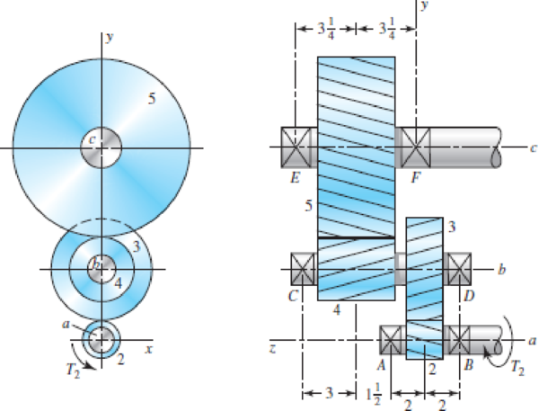
The figure shows a double-reduction helical gearset. Pinion 2 is the driver, and it receives a torque of 1200 lbf · in from its shaft in the direction shown. Pinion 2 has a normal diametral pitch of 8 teeth/in, 14 teeth, and a normal pressure angle of 20° and is cut right-handed with a helix angle of 30°. The mating gear 3 on shaft b has 36 teeth. Gear 4, which is the driver for the second pair of gears in the train, has a normal diametral pitch of 5 teeth/in, 15 teeth, and a normal pressure angle of 20° and is cut left-handed with a helix angle of 15°. Mating gear 5 has 45 teeth. Find the magnitude and direction of the force exerted by the bearings C and D on shaft b if bearing C can take only a radial load while bearing D is mounted to take both radial and thrust loads.
Problem 13–50
Dimensions in inches.
The magnitude and direction of the force exerted by the bearing
The magnitude and direction of the force exerted by the bearing
Answer to Problem 50P
The magnitude and direction of the force exerted by the bearing
The magnitude and direction of the force exerted by the bearing
Explanation of Solution
The figure below shows the forces acting on the assembly of gears on the shaft
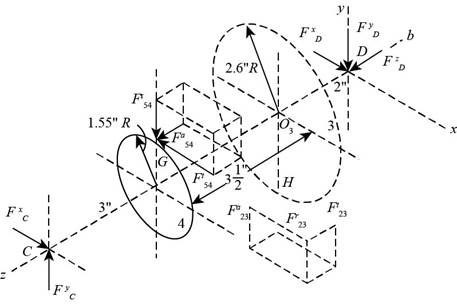
Figure-(1)
The center of the gear 3 is
Write the expression for the diameter of the gear 2.
Here, the number of teeth on the gear 2 is
Write the expression for the diameter of the gear 4.
Here, the number of teeth on the gear 2 is
Write the expression for the diameter of the gear 3.
Here, the number of teeth on the gear 3 is
Write the expression for the diameter of the gear 5.
Here, the number of teeth on the gear 5 is
Write the expression for the transverse pressure angle for gears 2.
Here, the normal pressure angle is
The transverse pressure angle for gears 2 and 3 are same.
Write the expression for the transverse pressure angle for gears 4.
Here, the normal pressure angle is
Write the expression for the tangential force on the gear 3.
Here, the torque on the gear 2 is
Write the expression for the radial force on the gear 3.
Write the expression for the axial force on the gear 3.
Calculate the tangential load on the gear 4.
Write the expression for the radial force on the gear 4.
Write the expression for the axial force on the gear 4.
Write the expression for the position vector for
Here, the length of
Write the expression for the position vector for
Here, the length of
Write the expression for the position vector for
Here, the length of
Write the expression for the force
Write the expression for the force
Write the expression for the force on the bearing
Write the expression for the force on the bearing
Write the expression for the moment at
Substitute
Write the expression for the force balance equation.
Conclusion:
Substitute
Substitute
Substitute
Substitute
Substitute
Substitute
Substitute
Substitute
Substitute
Substitute
Substitute
Substitute
Substitute
Further simplification,
Compare the
Compare the
Substitute
Substitute
Substitute
Substitute
Further simplification.
Compare the
Compare the
Compare the
Substitute
Thus, the force in the bearing
Substitute
Thus, the magnitude and direction of the force exerted by the bearing
Want to see more full solutions like this?
Chapter 13 Solutions
Shigley's Mechanical Engineering Design (McGraw-Hill Series in Mechanical Engineering)


- A pair of helical gears are machined with a hob. The hob has a 20 degree pressure angle and machines circular pitch of 0.55 inch/tooth on a spur gear. Two gears are machined, the pinion has 18 teeth and the gear has 36 teeth. The measured transverse diametral pitch on the pinion is 5 inch/tooth. The pinion transmits 10 hp at 1,000 rpm. Calculate the helix angle of the gearset, in degrees.arrow_forward187 13-40 The figure shows a pair of shaft-mounted spur gears having a diametral pitch of 5 teeth/in with an 18-tooth 20° pinion driving a 45-tooth gear. The power input is 32-hp at 1800 rev/min. Find the direction and magnitude of the forces acting on bearings A, B, C, and D. 13-41 The figure shows the electric-motor frame dimensions for a 30-hp 900 rev/min motor. The frame is bolted to its support using four -in bolts spaced 11 in apart in the view shown and 14 in apart when viewed from the end of the motor. A 4 diametral pitch 20° spur pinion having 20 teeth and a face width of 2 in is keved to and fluch with 3 in 3 in Problem 13-40arrow_forwardA parallel helical gearset uses a 20-tooth pinion driving a 46-tooth gear. The pinion has a righthand helix angle of 30◦, a normal pressure angle of 20◦, and a normal diametral pitch of 6 teeth/in. Find: (a) The normal, transverse, and axial circular pitches (b) The normal base circular pitch (c) The transverse diametral pitch and the transverse pressure angle (d) The addendum, dedendum, and pitch diameter of each geararrow_forward
- A 21-tooth spur pinion mates with a 28-tooth gear. The diametral pitch is 3 teeth/in and the pressure angle is 20°. Make a drawing of the gears showing one tooth on each gear. Find and tabulate the following results: the addéndum, dedendum, clearance, circular pitch, tooth thick- ness, and base-circle diameters; the lengths of the arc of approach, recess, and action; and the base pitch and contact ratio.arrow_forwardQ8:- An epicyclic gear speed reduction is shown in the Fig. below. The driving shaft carries on the arm A a pin on which the compound wheels B and C are free to revolve. Wheel C meshes with the fixed wheel E and wheel B meshes with the wheel D which is keyed to the driven shaft. The number of teeth on the wheels are:- Z=27, Z=30, Zp=24 and Ze=21. Find the ratio of the speed of the driving shaft to the speed of the driven shaft. Input D EN output Earrow_forwardA 28-tooth spur pinion mates with a 42-tooth gear. The diametral pitch is 4 teeth/in and the pressure angle is 20.. Make a drawing of the gears showing one tooth on each gear. Find and tabulate the following results: the addendum, dedendum, clearance, circular pitch, tooth thickness, and base-circle diameters; the lengths of the arc of approach, recess, and action; and the base pitch and contact ratio.arrow_forward
- A 20 straight-tooth bevel pinion having 14 teeth and a diametral pitch of 4 teeth/in drives a 30-tooth gear. The two shafts are at right angles and in the same plane. The illustration below shows a typical right-angle bevel gear set. Bevel gear pitch diameters are measured on the outside face along the back-cone, as shown in the figure. As shown in figure 13-35, the resultant force acts at the average radius of the gear/pinion. If the power transmitted by the pinion is 10 at 1,453 rpm, calculate the pinion tangent force in lbf. Cone distance A Face Pitch angle Pitch angle Back cone Uniform clearance Pitch diameter Da Back-cone radius, harrow_forwardi A parallel helical gearset uses a 18-tooth pinion driving a 35-tooth gear. The pinion has a righthand helix angle of 30-, a normal pressure angle of 20-, and a normal diametral pitch of 5.5 teeth in. Find: (a) The normal, transverse, and axial circular pitches (b) The nomal base circular pitch (c) The transverse diametral pitch and the transverse pressure angle (d) The addendum, dedendum, and pitch diameter of each gear Attach File Browse My Computerarrow_forwardProblem 1. The spur gears shown in Figure 1 have a diametral pitch of 2 teeth per inch and a 20° - pressure angle. Gear 2 rotates at 1800 rev/min clockwise and transmits 200 hp through the idler pair in Gear 5 on shaft c. (a) Show fully labeled free-body diagrams of gear 2, and Gears 3 and 4; (b) What forces do gear 3 and 4 transmit to the idler shaft? (c) What is the train value? (d) What is the output speed? Gear 5 Gear 4 48Teeth 18Teeth Gear 3 32Teeth Gear 2 18Teeth Figure 1arrow_forward
- The figure shows a schematic representation of a gear system. The gears are meshed with one another and can therefore not slip. The ring gear R is fixed, i.e. wR = 0. Gear A has an inner hub with radius rA(inner) = 0.3 m which is fixed to the rest of the gear, having a radius of FAlouter) = 0.8 m, and moves together as a unit. Gear A is in mesh with gear B which has a diameter of de = 1.5 m. Gear B has a clockwise angular velocity of wg = 2.1 rad/s. Determine the angular speed of gear A. B TA(outer Rarrow_forwardThe teeth of the gear arrangement have Gear A=40teeth, Gear B=70 teeth and Gear C= 50teeth, a pinion (driver Gear) that rotates at 625 rpm, and idler Gear B and a driven gear (Gear C). The gears have a module of 5mm and a pressure angle of 200. Find the pitch diameter of gear C in mm.arrow_forwardQuestion 1 A pickup truck is driving at a speed of 100 km/h on a leveled road. This truck has4 wheels of the same diameter of 400 mm and drives at a gear ratio of 5 to 1 if its gearbox 5th gear is selected. The gear’s teeth are of involute form with a module of 8 mm, an addendum is double the module, and the pressure angle is equal to 20°. 1(a). If the driving shaft of the front wheels of the truck is connected to the output shaft of the gearbox, determine the number of teeth on the pinion to avoid interference and the corresponding number of teeth on the gear wheel. 1(b) Calculate the gear maximum velocity of sliding.arrow_forward
 Elements Of ElectromagneticsMechanical EngineeringISBN:9780190698614Author:Sadiku, Matthew N. O.Publisher:Oxford University Press
 Mechanics of Materials (10th Edition)Mechanical EngineeringISBN:9780134319650Author:Russell C. HibbelerPublisher:PEARSON
 Thermodynamics: An Engineering ApproachMechanical EngineeringISBN:9781259822674Author:Yunus A. Cengel Dr., Michael A. BolesPublisher:McGraw-Hill Education
 Control Systems EngineeringMechanical EngineeringISBN:9781118170519Author:Norman S. NisePublisher:WILEY
 Mechanics of Materials (MindTap Course List)Mechanical EngineeringISBN:9781337093347Author:Barry J. Goodno, James M. GerePublisher:Cengage Learning
 Engineering Mechanics: StaticsMechanical EngineeringISBN:9781118807330Author:James L. Meriam, L. G. Kraige, J. N. BoltonPublisher:WILEY