
Concept explainers
Videos
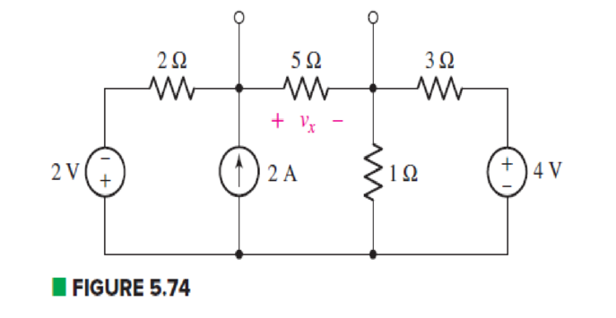
Determine the Norton equivalent of the circuit depicted in Fig. 5.74 as seen looking into the two open terminals. (b) Compute power dissipated in a 5 Ω resistor connected in parallel with the existing 5 Ω resistor. (c) Compute the current flowing through a short circuit connecting the two terminals.
(a)
Find the Norton equivalent of the circuit as seen looking into the two open terminals.
Answer to Problem 33E
The Norton current is
Explanation of Solution
Formula used:
The expression for voltage is as follows.
Here,
The expression for series combination of resistance is as follows.
Here,
The expression for parallel combination of resistance is as follows.
Here,
Calculation:
The circuit diagram is redrawn as shown in Figure 1.
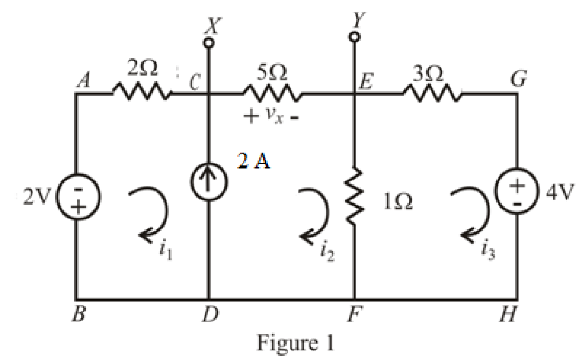
Refer to redrawn Figure 1,
The expression for KVL in super mesh
Here,
Substitute
The expression for KVL in mesh
Here,
Substitute
The expression for current
Here,
Substitute
Rearrange equations(5),(7) and (9).
The equations so formed can be written in matrix form as,
Therefore, by Cramer’s rule,
The determinant of coefficient matrix is as follows.
The 1st determinant is as follows.
The 2nd determinant is as follows,
The 3rd determinant is as follows.
Simplify for
Simplify for
Simplify for
Substitute
So, the Thevenin voltage is
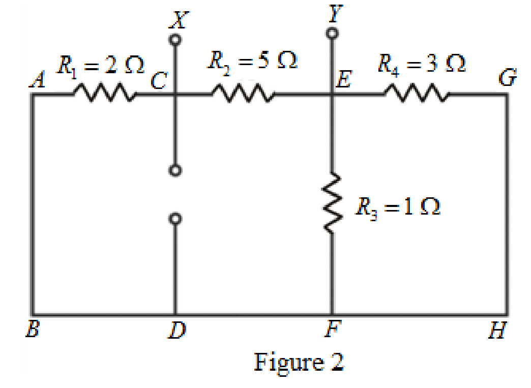
The circuit diagram is redrawn as shown in Figure 2.
As
Rearrange for
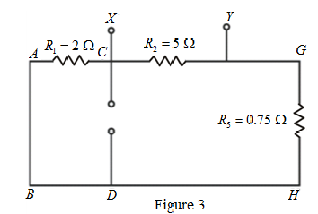
The circuit diagram is redrawn as shown in Figure 3.
As
The circuit diagram is redrawn as shown in Figure 4.
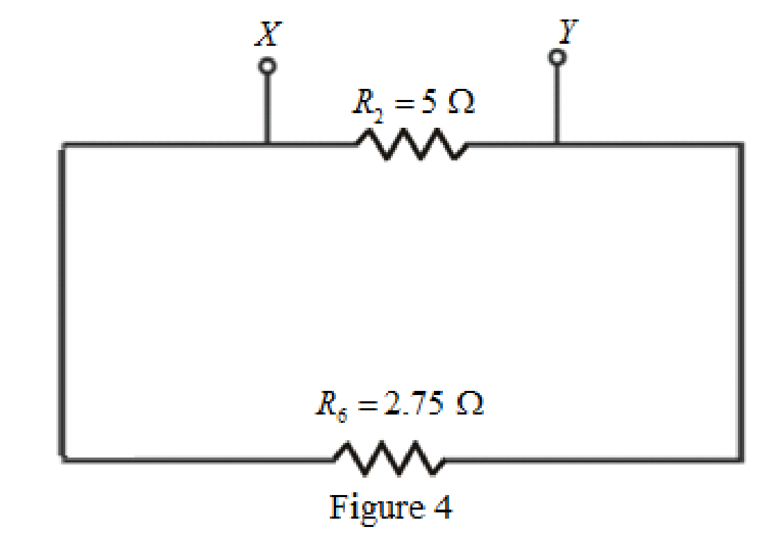
Refer to redrawn Figure 4,
As
Rearrange for
So, the Thevenin equivalent resistance across the branch
Thevenin equivalent resistance is same as the Norton equivalent resistance,
Hence,
The circuit diagram is redrawn as shown in Figure 5,
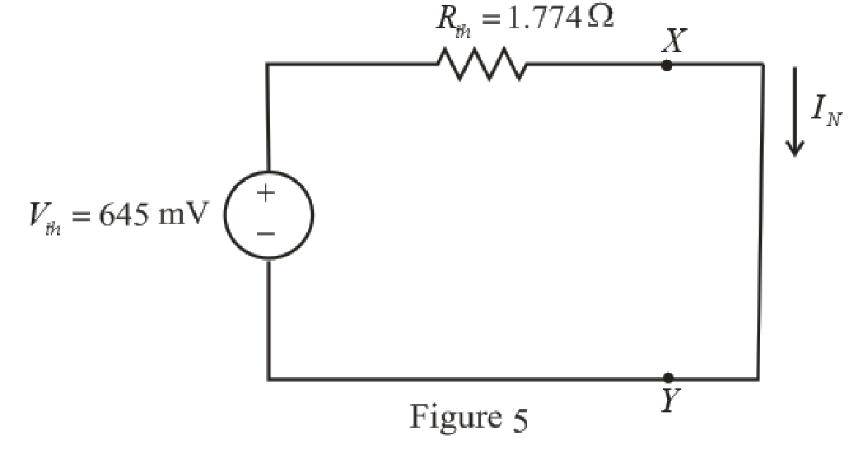
Refer to redrawn Figure 5,
Norton current is the current in the load resistor when load resistance is replaced by a short circuit.
The expression for the Norton current flowing in the circuit is as follows,
Here,
Substitute
Conclusion:
Thus the Norton current is
(b)
Find the power dissipated in a
Answer to Problem 33E
The power dissipated in a
Explanation of Solution
Given Data:
The load resistance is
Formula used:
The expression for the power dissipated in a resistor is as follows,
Here,
Calculation:
The circuit is drawn as shown in Figure 6,
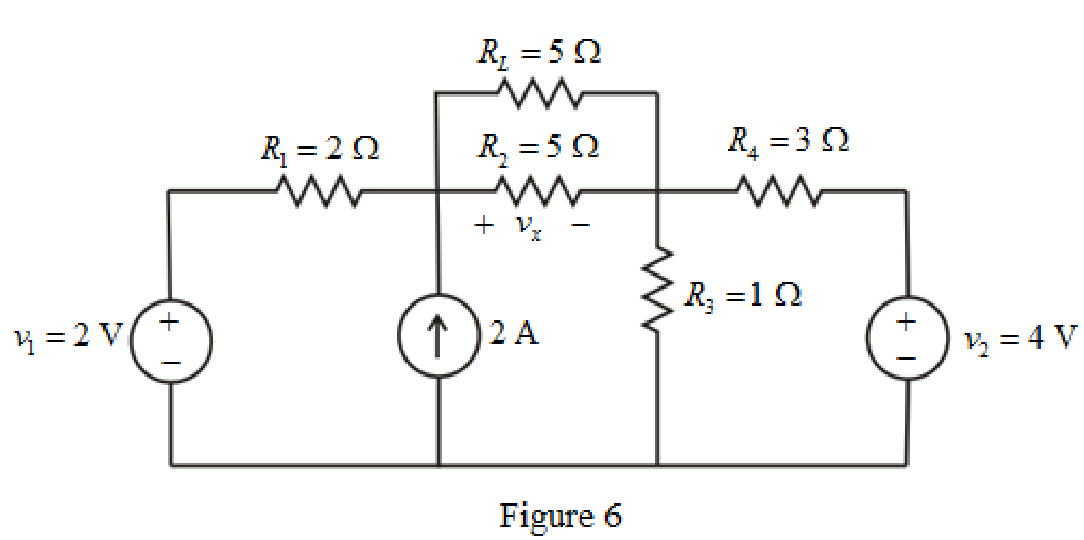
Refer to redrawn Figure 6,
The simplified Norton equivalent of the circuit is drawn as shown in Figure 7,
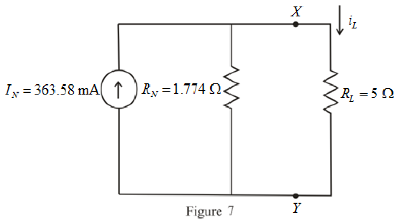
Refer to redrawn Figure 7,
The expression for the current flowing through the load is as follows,
Substitute
Substitute
Conclusion:
Thus, the power dissipated in a
(c)
Find the current flowing through a short circuit connecting the two terminals.
Answer to Problem 33E
The current flowing through a short circuit connecting the two terminals is
Explanation of Solution
Calculation:
The current flowing through a short circuit connecting the two terminals is Norton current which is
So, the current flowing through a short circuit connecting the two terminals is
Conclusion:
Thus, the current flowing through a short circuit connecting the two terminals is
Want to see more full solutions like this?
Chapter 5 Solutions
Loose Leaf for Engineering Circuit Analysis Format: Loose-leaf


- Using the voltage divider rule or Kirchhoff's voltage law, determine the unknown voltages for the configurations in Fig. 5.119. Do not calculate the current! E₁ + • 50 V + wwwwww 3.3 ΚΩ + V = www 6.8 ΚΩ 4.7 ΚΩ 10 ΚΩ 30 V Ο + Vx E + 2 Ω 68 Ω 100 Ω Μ W www +1 + 1 + 1000 V | UNIVERSarrow_forwardHomework: Obtain vo in the circuit of the following figure. 5.3 30 V 20 V 4 k2 2 kn 5 kn Answer 20 V www wwarrow_forwardConsider the circuit shown below. [5] Determine and sketch the Norton equivalent circuit and indicate all element values clearly. 5Ωarrow_forward
- Using Kirchhoff's voltage law, find the unknown voltages for the configurations in Fig. 5.107. 20 V + V₁ - - IV + + 10 V ō +2V- www www - V₂ + 10 V + V₁ - www V₂ - 6V + +||| - 3V+ 2 Varrow_forwardFind the voltage across each resistor in Fig. 5.116 if R1 = 2R3 and R2 =7R3. E 60 V R₁ R₂ R3 www +51 +51 +5 IN UNIVERSITYarrow_forwardHomework: Obtain vo in the circuit of the following figure. 5.3 30 V 20 V 4 k2 2 k2 3 k2 Answer 20 V wwarrow_forward
- For the series configuration in Fig . 5.98 constructed using standard value resistor without making a single calculation, which resistive element will have the most voltage across it? Which will have the least? which resistor will have the most impact on the total resistance and the the resulting current ? Find the total resistance and the current. Find the voltage across each element and review your response to part (a)arrow_forwardFor the series configuration in Fig. 5.92, constructed using standard value resistors: a.) Without making a single calculation, which resistive element will have the most voltage across it? Which will have the least? b.) Which resistor will have the most impact on the total resistance and the resulting current? Find the total resistance and the current.arrow_forwardUsing the voltage divider rule or Kirchhoff's voltage law, determine the unknown voltages for the configurations in Fig. 5.119. Do not calculate the current! E₁ + 50 V + E • 3.3 ΚΩ + Vi 6.8 ΚΩ · 4.7 ΚΩ WHI • 10 ΚΩ 30 V 0 + Vx E HI 2 Ω 68 Ω 100 Ω Μ + + 1000 V - UNIVERSarrow_forward
- Question 48 Study the circuit of Fig. 5.89. a) Determine the Norton equivalent connected to resistor Rout. b) Select a value for Rout such that maximum power will be delivered to it. 4 A FIGURE 5.89 ΚΩ 3 V 2 V 2 kΩ Routarrow_forwardFind the voltage across each resistor in Fig. 5.123 if R1 = 2R3 and R2 = 7R3. E + 80 V R₁ R₂ R3 www +1+1+1arrow_forwardApply Mesh Analysis and Node Voltage Methods to Example 5.2-3) i.e., solve for i in terms of R. 12 V 1+ 4 ΚΩ M 2 mA Rarrow_forward
 Introductory Circuit Analysis (13th Edition)Electrical EngineeringISBN:9780133923605Author:Robert L. BoylestadPublisher:PEARSON
 Delmar's Standard Textbook Of ElectricityElectrical EngineeringISBN:9781337900348Author:Stephen L. HermanPublisher:Cengage Learning
 Programmable Logic ControllersElectrical EngineeringISBN:9780073373843Author:Frank D. PetruzellaPublisher:McGraw-Hill Education
 Fundamentals of Electric CircuitsElectrical EngineeringISBN:9780078028229Author:Charles K Alexander, Matthew SadikuPublisher:McGraw-Hill Education
 Electric Circuits. (11th Edition)Electrical EngineeringISBN:9780134746968Author:James W. Nilsson, Susan RiedelPublisher:PEARSON
 Engineering ElectromagneticsElectrical EngineeringISBN:9780078028151Author:Hayt, William H. (william Hart), Jr, BUCK, John A.Publisher:Mcgraw-hill Education,