
Loose Leaf for Engineering Circuit Analysis Format: Loose-leaf
9th Edition
ISBN: 9781259989452
Author: Hayt
Publisher: Mcgraw Hill Publishers
expand_more
expand_more
format_list_bulleted
Concept explainers
Videos
Textbook Question
Chapter 5, Problem 69E
A load resistor is connected across the open terminals of the circuit shown in Fig. 5.107, and its value was chosen carefully to ensure maximum power transfer from the rest of the circuit. (a) What is the value of the resistor? (b) If the power absorbed by the load resistor is three times as large as required, modify the circuit so that it performs as desired, without losing the maximum power transfer condition already enjoyed.
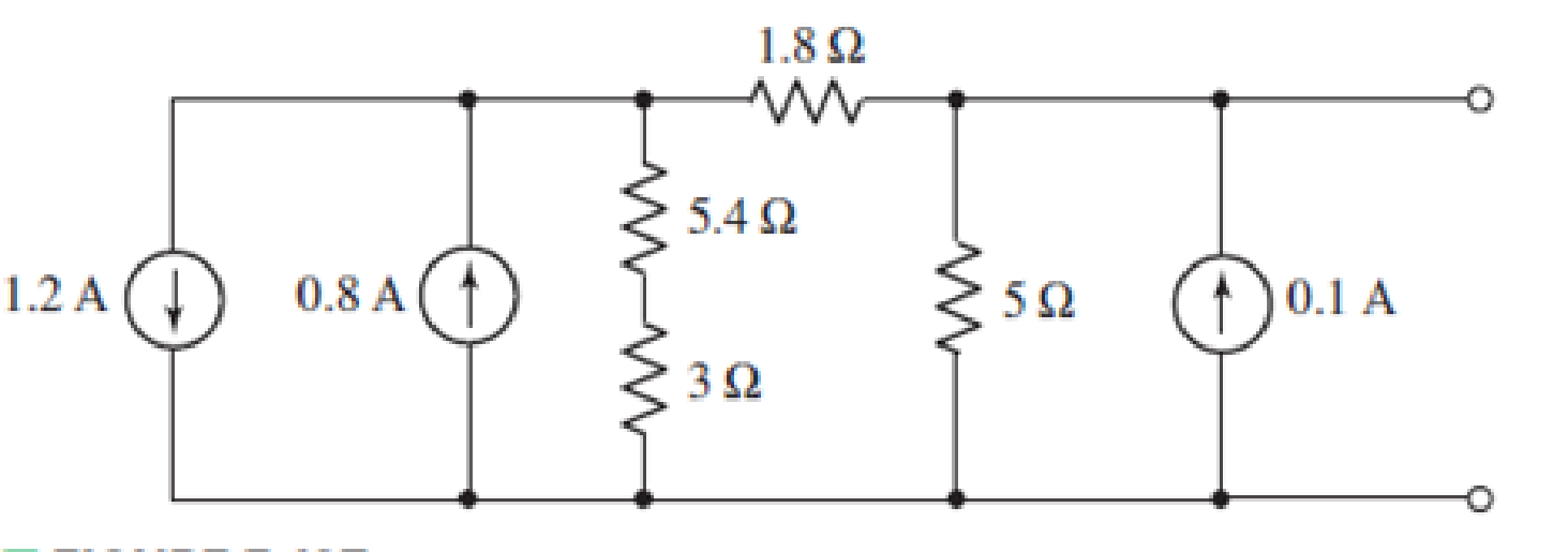
FIGURE 5.107
Expert Solution & Answer
Want to see the full answer?
Check out a sample textbook solution
Students have asked these similar questions
For the series configuration in Fig. 5.92, constructed using standard value resistors:
a.) Without making a single calculation, which resistive element will have the most voltage across it? Which will have the least?
b.) Which resistor will have the most impact on the total resistance and the resulting current? Find the total resistance and the current.
Homework:
Obtain vo in the circuit of the following figure.
5.3
30 V
20 V
4 k2
2 k2
3 k2
Answer
20 V
ww
Homework:
Obtain vo in the circuit of the following figure.
5.3
30 V
20 V
4 kS2
2 k2
5 k2
Answer
20 V
Chapter 5 Solutions
Loose Leaf for Engineering Circuit Analysis Format: Loose-leaf
Ch. 5.1 - For the circuit of Fig. 5.4, use superposition to...Ch. 5.2 - For the circuit of Fig. 5.7, use superposition to...Ch. 5.2 - For the circuit of Fig. 5.18, compute the current...Ch. 5.2 - For the circuit of Fig. 5.20, compute the voltage...Ch. 5.3 - Using repeated source transformations, determine...Ch. 5.3 - Use Thvenins theorem to find the current through...Ch. 5.3 - Determine the Thvenin and Norton equivalents of...Ch. 5.3 - Find the Thvenin equivalent for the network of...Ch. 5.3 - Find the Thvenin equivalent for the network of...Ch. 5.4 - Consider the circuit of Fig. 5.43. FIGURE 5.43...
Ch. 5.5 - Prob. 11PCh. 5 - Linear systems are so easy to work with that...Ch. 5 - Prob. 2ECh. 5 - Prob. 3ECh. 5 - (a) Employ superposition to determine the current...Ch. 5 - (a) Using superposition to consider each source...Ch. 5 - (a) Determine the individual contributions of each...Ch. 5 - (a) Determine the individual contributions of each...Ch. 5 - After studying the circuit of Fig. 5.53, change...Ch. 5 - Consider the three circuits shown in Fig. 5.54....Ch. 5 - (a) Using superposition, determine the voltage...Ch. 5 - Employ superposition principles to obtain a value...Ch. 5 - (a) Employ superposition to determine the...Ch. 5 - Perform an appropriate source transformation on...Ch. 5 - (a) For the circuit of Fig. 5.59, plot iL versus...Ch. 5 - Determine the current labeled I in the circuit of...Ch. 5 - Verify that the power absorbed by the 7 resistor...Ch. 5 - (a) Determine the current labeled i in the circuit...Ch. 5 - (a) Using repeated source transformations, reduce...Ch. 5 - Prob. 19ECh. 5 - (a) Making use of repeated source transformations,...Ch. 5 - Prob. 21ECh. 5 - (a) With the assistance of source transformations,...Ch. 5 - For the circuit in Fig. 5.67 transform all...Ch. 5 - Prob. 24ECh. 5 - (a) Referring to Fig. 5.69, determine the Thevenin...Ch. 5 - (a) With respect to the circuit depicted in Fig....Ch. 5 - (a) Obtain the Norton equivalent of the network...Ch. 5 - (a) Determine the Thevenin equivalent of the...Ch. 5 - Referring to the circuit of Fig. 5.71: (a)...Ch. 5 - Prob. 30ECh. 5 - (a) Employ Thvenins theorem to obtain a...Ch. 5 - Prob. 32ECh. 5 - Determine the Norton equivalent of the circuit...Ch. 5 - For the circuit of Fig. 5.75: (a) Employ Nortons...Ch. 5 - (a) Obtain a value for the Thvenin equivalent...Ch. 5 - Prob. 36ECh. 5 - Obtain a value for the Thvenin equivalent...Ch. 5 - With regard to the network depicted in Fig. 5.79,...Ch. 5 - Determine the Thvenin and Norton equivalents of...Ch. 5 - Determine the Norton equivalent of the circuit...Ch. 5 - Prob. 41ECh. 5 - Determine the Thvenin and Norton equivalents of...Ch. 5 - Prob. 43ECh. 5 - Prob. 44ECh. 5 - Prob. 45ECh. 5 - (a) For the simple circuit of Fig. 5.87, find the...Ch. 5 - For the circuit drawn in Fig. 5.88, (a) determine...Ch. 5 - Study the circuit of Fig. 5.89. (a) Determine the...Ch. 5 - Prob. 49ECh. 5 - Prob. 50ECh. 5 - With reference to the circuit of Fig. 5.91, (a)...Ch. 5 - Prob. 52ECh. 5 - Select a value for RL in Fig. 5.93 such that it...Ch. 5 - Determine what value of resistance would absorb...Ch. 5 - Derive the equations required to convert from a...Ch. 5 - Convert the - (or "-") connected networks in Fig....Ch. 5 - Convert the Y-(or T-) connected networks in Fig....Ch. 5 - For the network of Fig. 5.97, select a value of R...Ch. 5 - For the network of Fig. 5.98, select a value of R...Ch. 5 - Prob. 60ECh. 5 - Calculate Rin as indicated in Fig.5.100. FIGURE...Ch. 5 - Employ Y conversion techniques as appropriate to...Ch. 5 - Prob. 63ECh. 5 - (a) Use appropriate techniques to obtain both the...Ch. 5 - (a) For the network in Fig. 5.104, replace the...Ch. 5 - Prob. 66ECh. 5 - Prob. 67ECh. 5 - A 2.57 load is connected between terminals a and...Ch. 5 - A load resistor is connected across the open...Ch. 5 - A backup is required for the circuit depicted in...Ch. 5 - (a) Explain in general terms how source...Ch. 5 - The load resistor in Fig. 5.108 can safely...Ch. 5 - Prob. 74ECh. 5 - As part of a security system, a very thin 100 ...Ch. 5 - With respect to the circuit in Fig. 5.90, (a)...
Knowledge Booster


Learn more about
Need a deep-dive on the concept behind this application? Look no further. Learn more about this topic, electrical-engineering and related others by exploring similar questions and additional content below.Similar questions
- Using the voltage divider rule or Kirchhoff's voltage law, determine the unknown voltages for the configurations in Fig. 5.119. Do not calculate the current! E₁ + • 50 V + wwwwww 3.3 ΚΩ + V = www 6.8 ΚΩ 4.7 ΚΩ 10 ΚΩ 30 V Ο + Vx E + 2 Ω 68 Ω 100 Ω Μ W www +1 + 1 + 1000 V | UNIVERSarrow_forwardUsing the voltage divider rule or Kirchhoff's voltage law, determine the unknown voltages for the configurations in Fig. 5.119. Do not calculate the current! E₁ + 50 V + E • 3.3 ΚΩ + Vi 6.8 ΚΩ · 4.7 ΚΩ WHI • 10 ΚΩ 30 V 0 + Vx E HI 2 Ω 68 Ω 100 Ω Μ + + 1000 V - UNIVERSarrow_forward5.2 For the circuit of Fig. 5.7, use superposition to obtain the voltage across each current source. Ans: Viha = 9.180 V, v2zA =-1.148 V, UIlay = 1.967 V, v2by = -0.246 V; vI = 11.147 V, vz = -1.394 V. %3D %3D %3D 15 N 12 4i 2 A( 3 Varrow_forward
- Homework: Obtain vo in the circuit of the following figure. 5.3 30 V 20 V 4 k2 2 kn 5 kn Answer 20 V www wwarrow_forwardGiven the circuit below. The current through the 100 resistor in the circuit below is 8.0 mA. Determine the 2002 5.0 (2 [www] 10:2 a) total resistance b) total current c) total voltage 30 2 www wwww 5.002 4002arrow_forwardFor the configuration in fig . 5.116, with standard resistor values : by inspection , which resistor will receive the largest share of the applied voltage ? Why? how much larger will voltage V3 be compared to V2 and V1 Find the voltage across the largest resistor using the the voltage divider rule Find the voltage across the series combination of resistors R2 and R3arrow_forward
- For the circuit in Fig. 5.88, composed of standard values: a. Which resistor will have the most impact on the total resistance? b. On an approximate basis, which resistors can be ignored when determining the total resistance? c. Find the total resistance, and comment on your results for parts (a) and (b).arrow_forwardExample: 5.1 Calculate the node voltages in the circuit shown in the below figure: 5 A 42 21 22 10 Aarrow_forwardFind the voltage across each resistor in Fig. 5.116 if R1 = 2R3 and R2 =7R3. E 60 V R₁ R₂ R3 M M M 15² +15+15+ UNIVERSITYarrow_forward
- Find the total resistance R, for each configuration in Fig. 5.86. Note that only standard resistor values were used. R R3 R3 R 0.39 kn 12 kn 1.20 2.7A RT R, (a) (b) R 82 kl 47A R 10kn R, {1 kn R4 Ry 1.8 n R.4, 820n R R, 12 kl 91 0 27 kn (c) (d) FIG. 5.86arrow_forwardUsing Kirchhoff's voltage law, find the unknown voltages for the configurations in Fig. 5.107. 20 V + V₁ - www www - IV + + 10 V ō + 2V www - V₂ + 10 V + + V₁ + www V₂ -6V+ +|₁| www - 3V + 2 Varrow_forwardFor each configuration in Fig. 5.85, find the individual (not combinations of) elements (voltages sources and/or resistors) that are in series. If necessary, use the fact that elements in series have the same current. Simply list those that satisfy the conditions for a series relationship.arrow_forward
arrow_back_ios
SEE MORE QUESTIONS
arrow_forward_ios
Recommended textbooks for you
 Introductory Circuit Analysis (13th Edition)Electrical EngineeringISBN:9780133923605Author:Robert L. BoylestadPublisher:PEARSON
 Delmar's Standard Textbook Of ElectricityElectrical EngineeringISBN:9781337900348Author:Stephen L. HermanPublisher:Cengage Learning
 Programmable Logic ControllersElectrical EngineeringISBN:9780073373843Author:Frank D. PetruzellaPublisher:McGraw-Hill Education
 Fundamentals of Electric CircuitsElectrical EngineeringISBN:9780078028229Author:Charles K Alexander, Matthew SadikuPublisher:McGraw-Hill Education
 Electric Circuits. (11th Edition)Electrical EngineeringISBN:9780134746968Author:James W. Nilsson, Susan RiedelPublisher:PEARSON
 Engineering ElectromagneticsElectrical EngineeringISBN:9780078028151Author:Hayt, William H. (william Hart), Jr, BUCK, John A.Publisher:Mcgraw-hill Education,
Introductory Circuit Analysis (13th Edition)
Electrical Engineering
ISBN:9780133923605
Author:Robert L. Boylestad
Publisher:PEARSON
Delmar's Standard Textbook Of Electricity
Electrical Engineering
ISBN:9781337900348
Author:Stephen L. Herman
Publisher:Cengage Learning
Programmable Logic Controllers
Electrical Engineering
ISBN:9780073373843
Author:Frank D. Petruzella
Publisher:McGraw-Hill Education
Fundamentals of Electric Circuits
Electrical Engineering
ISBN:9780078028229
Author:Charles K Alexander, Matthew Sadiku
Publisher:McGraw-Hill Education
Electric Circuits. (11th Edition)
Electrical Engineering
ISBN:9780134746968
Author:James W. Nilsson, Susan Riedel
Publisher:PEARSON
Engineering Electromagnetics
Electrical Engineering
ISBN:9780078028151
Author:Hayt, William H. (william Hart), Jr, BUCK, John A.
Publisher:Mcgraw-hill Education,
Current Divider Rule; Author: Neso Academy;https://www.youtube.com/watch?v=hRU1mKWUehY;License: Standard YouTube License, CC-BY