
Loose Leaf for Engineering Circuit Analysis Format: Loose-leaf
9th Edition
ISBN: 9781259989452
Author: Hayt
Publisher: Mcgraw Hill Publishers
expand_more
expand_more
format_list_bulleted
Videos
Textbook Question
Chapter 5, Problem 73E
The load resistor in Fig. 5.108 can safely dissipate up to 1 W before overheating and bursting into flame. The lamp can be treated as a 10.6 Ω resistor if less than 1 A flows through it and a 15 Ω resistor if more than 1 A flows through it. What is the maximum permissible value of Is? Verify your answer with an appropriate computer simulation.
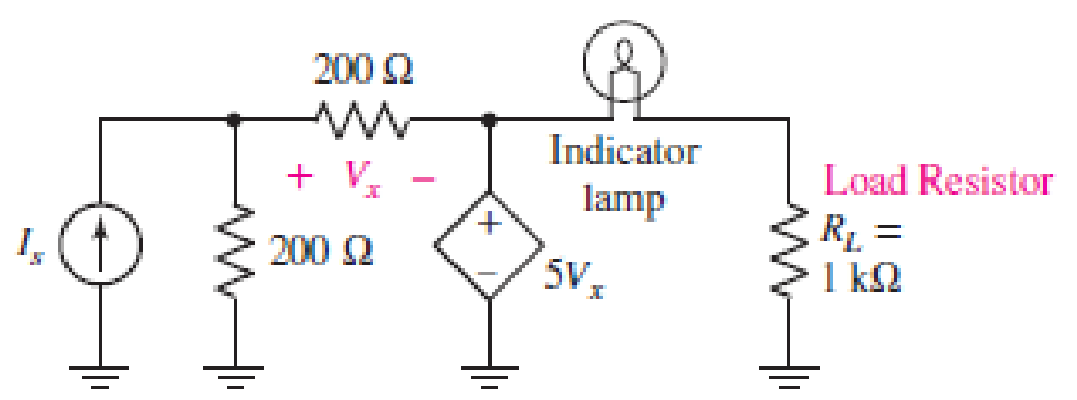
■ FIGURE 5.108
Expert Solution & Answer
Want to see the full answer?
Check out a sample textbook solution
Students have asked these similar questions
how long will it take to charge a 1000μF capacitor through 1 KQ resistor to
full 16V source voltage? d) forever
a) 1000 microseconds
b) 10seconds
c) one day
d)
forever
What maximum voltage can be safely applied to series resistors, 1.2 KQ ¹4 W
and 680 0%W?
a) 9.81V
b) 17.32. V
c)27.07 V
d) 32.52V
When a capacitor is being charged from a 12V power source, the current
flowing through thecapacitor will
a} increase
b} decrease
c) remain the same
d) can't be determined
Calculate the voltmeter reading in the circuit shown in the figure when wiper
arm of the potentiometer is set at 25% up fromthe bottom. note: the
resistance value is 3.3 Kilo-ohms.
9V
Oa) 2.13 V
b) 3.12 V
c)2.31 V
d) 6.25 V
1k
3k3
how long will it take to charge a 1000μF capacitor through 1 KQ resistor to
full 16V source voltage? d) forever
a) 1000 microseconds
b) 10seconds
c) one day
d) forever
What maximum voltage can be safely applied to series resistors, 1.2 KQ 14 W
and 680 0%W?
a) 9.81V
b) 17.32. V
c)27.07 V
d) 32.52V
When a capacitor is being charged from a 12V power source, the current
flowing through thecapacitor will
a} increase
b} decrease
c) remain the same
d) can't be determined
Calculate the voltmeter reading in the circuit shown in the figure when wiper
arm of the potentiometer is set at 25% up fromthe bottom. note: the
resistance value is 3.3 Kilo-ohms.
9V
a) 2.13 V
b) 3.12 V
c)2.31 V
d) 6.25 V
1k
3k3
A moving coil instrument gives a full scale deflection of 10mA when the potential difference a cross its terminal is 100mV. Calculate
1) The shunt resistance for a full scale deflection corresponding to 100A
ii) The series resistance for full scale reading with 1000V
ⅲ) Calculate power dissipation in each case
Chapter 5 Solutions
Loose Leaf for Engineering Circuit Analysis Format: Loose-leaf
Ch. 5.1 - For the circuit of Fig. 5.4, use superposition to...Ch. 5.2 - For the circuit of Fig. 5.7, use superposition to...Ch. 5.2 - For the circuit of Fig. 5.18, compute the current...Ch. 5.2 - For the circuit of Fig. 5.20, compute the voltage...Ch. 5.3 - Using repeated source transformations, determine...Ch. 5.3 - Use Thvenins theorem to find the current through...Ch. 5.3 - Determine the Thvenin and Norton equivalents of...Ch. 5.3 - Find the Thvenin equivalent for the network of...Ch. 5.3 - Find the Thvenin equivalent for the network of...Ch. 5.4 - Consider the circuit of Fig. 5.43. FIGURE 5.43...
Ch. 5.5 - Prob. 11PCh. 5 - Linear systems are so easy to work with that...Ch. 5 - Prob. 2ECh. 5 - Prob. 3ECh. 5 - (a) Employ superposition to determine the current...Ch. 5 - (a) Using superposition to consider each source...Ch. 5 - (a) Determine the individual contributions of each...Ch. 5 - (a) Determine the individual contributions of each...Ch. 5 - After studying the circuit of Fig. 5.53, change...Ch. 5 - Consider the three circuits shown in Fig. 5.54....Ch. 5 - (a) Using superposition, determine the voltage...Ch. 5 - Employ superposition principles to obtain a value...Ch. 5 - (a) Employ superposition to determine the...Ch. 5 - Perform an appropriate source transformation on...Ch. 5 - (a) For the circuit of Fig. 5.59, plot iL versus...Ch. 5 - Determine the current labeled I in the circuit of...Ch. 5 - Verify that the power absorbed by the 7 resistor...Ch. 5 - (a) Determine the current labeled i in the circuit...Ch. 5 - (a) Using repeated source transformations, reduce...Ch. 5 - Prob. 19ECh. 5 - (a) Making use of repeated source transformations,...Ch. 5 - Prob. 21ECh. 5 - (a) With the assistance of source transformations,...Ch. 5 - For the circuit in Fig. 5.67 transform all...Ch. 5 - Prob. 24ECh. 5 - (a) Referring to Fig. 5.69, determine the Thevenin...Ch. 5 - (a) With respect to the circuit depicted in Fig....Ch. 5 - (a) Obtain the Norton equivalent of the network...Ch. 5 - (a) Determine the Thevenin equivalent of the...Ch. 5 - Referring to the circuit of Fig. 5.71: (a)...Ch. 5 - Prob. 30ECh. 5 - (a) Employ Thvenins theorem to obtain a...Ch. 5 - Prob. 32ECh. 5 - Determine the Norton equivalent of the circuit...Ch. 5 - For the circuit of Fig. 5.75: (a) Employ Nortons...Ch. 5 - (a) Obtain a value for the Thvenin equivalent...Ch. 5 - Prob. 36ECh. 5 - Obtain a value for the Thvenin equivalent...Ch. 5 - With regard to the network depicted in Fig. 5.79,...Ch. 5 - Determine the Thvenin and Norton equivalents of...Ch. 5 - Determine the Norton equivalent of the circuit...Ch. 5 - Prob. 41ECh. 5 - Determine the Thvenin and Norton equivalents of...Ch. 5 - Prob. 43ECh. 5 - Prob. 44ECh. 5 - Prob. 45ECh. 5 - (a) For the simple circuit of Fig. 5.87, find the...Ch. 5 - For the circuit drawn in Fig. 5.88, (a) determine...Ch. 5 - Study the circuit of Fig. 5.89. (a) Determine the...Ch. 5 - Prob. 49ECh. 5 - Prob. 50ECh. 5 - With reference to the circuit of Fig. 5.91, (a)...Ch. 5 - Prob. 52ECh. 5 - Select a value for RL in Fig. 5.93 such that it...Ch. 5 - Determine what value of resistance would absorb...Ch. 5 - Derive the equations required to convert from a...Ch. 5 - Convert the - (or "-") connected networks in Fig....Ch. 5 - Convert the Y-(or T-) connected networks in Fig....Ch. 5 - For the network of Fig. 5.97, select a value of R...Ch. 5 - For the network of Fig. 5.98, select a value of R...Ch. 5 - Prob. 60ECh. 5 - Calculate Rin as indicated in Fig.5.100. FIGURE...Ch. 5 - Employ Y conversion techniques as appropriate to...Ch. 5 - Prob. 63ECh. 5 - (a) Use appropriate techniques to obtain both the...Ch. 5 - (a) For the network in Fig. 5.104, replace the...Ch. 5 - Prob. 66ECh. 5 - Prob. 67ECh. 5 - A 2.57 load is connected between terminals a and...Ch. 5 - A load resistor is connected across the open...Ch. 5 - A backup is required for the circuit depicted in...Ch. 5 - (a) Explain in general terms how source...Ch. 5 - The load resistor in Fig. 5.108 can safely...Ch. 5 - Prob. 74ECh. 5 - As part of a security system, a very thin 100 ...Ch. 5 - With respect to the circuit in Fig. 5.90, (a)...
Knowledge Booster


Learn more about
Need a deep-dive on the concept behind this application? Look no further. Learn more about this topic, electrical-engineering and related others by exploring similar questions and additional content below.Similar questions
- Consider the figure below. (Due to the nature of this problem, do not use rounded intermediate values in your calculations-including answers submitted in WebAssign.) C2 0.300 µF (a) Find the charge stored on each capacitor in the figure shown above (C1 = 19.6 µF, C2 = 9.26 µF) when a 1.85 V battery is connected to the combination. Q1 = 3.724e-7 Q2 = 1.7594e-7 C Q3 = 5.4945e-7 (b) What energy is stored in each capacitor? E1 = How is energy stored related to the charge and capacitance? J Ez = How is energy stored related to the charge and capacitance? ) E3 = How is energy stored related to the charge and capacitance? Jarrow_forwarda) Referring to the circuit in Figure 3, the current and the voltage have reached to its final value. Determine: i The current, i. The voltage across 5a resistor. i. The voltage across 20 ka resistor 50 25 mH R, 20 ko 12 V 10 ka Figure 3 b) Referring to Figure 4, assume that all the currents and voltages have reached their final value. Given the value for inductance, L = 5 mH, L2 = 20 mH and capacitance C = 5 µF. Determine: i The current, h, , and le il. The voltage across the capacitor. i. The energy stored by the capacitor and inductor 50 IT 15 V Rs 20 0 R2 Figure 4arrow_forwardA sensitive ammeter (micro-ammeter) is used to manufacture an analog DC voltmeter. The ammeter has the characteristics: 100µA full-scale indication, internal resistance Ri=200ohm. Voltmeter Rs V R = Ri HA Measured_Voltage Calculate the series resistor Rs to obtain a voltmeter able to measure 50V (full scale). 5.9kohm 6kohm 119.9kohm 120kohm 199.5kohm 200kohm 499.8kohm 500kohm (hparrow_forward
- Show the solutions. 23. A 12-V battery is connected in series with a 30 ohms resistor and a 220 mH inductor. How long will it take for the current to reach half its maximum possible value? Answer: 5.08 ms 24. A coil having inductance L = 2.4 H and R = 4 ohms is connected to a constant 100 V dc source. How long does it take the voltage across the resistance to reach 50 V? Answer: 0.4158 sarrow_forwardGiven the circuit below, which of the below value(s) would change if the inductance value were doubled? Assume the circuit has been in this position for some time prior to the switching event happening. Multiple correct answers may exist. Select any/all that apply! t=0 30 12 V (+ 3H 202 40: energy stored prior to the switching event inductor current initial condition time constant energy stored when the system reaches steady-state inductor current final condition None of these answers are correct 402arrow_forwardThe terminal voltage of a battery is 13.5 v when 5 A current enters its positive terminal, but when a 5 A current leaves its positive terminal, the terminal voltage becomes 11.5 v. Determine the EMF and internal resistance of this battery. (8 = ?, r =?)arrow_forward
- Design 7-step Voltmeter and 3-step Ammeter using galvanometer as integrated. (You can choose the current and voltage values but the design must be integrated.)arrow_forwardGiven the circuit below. The current through the 100 resistor in the circuit below is 8.0 mA. Determine the 2002 5.0 (2 [www] 10:2 a) total resistance b) total current c) total voltage 30 2 www wwww 5.002 4002arrow_forwardA battery with EMF of 7V and an internal resistance, r=0.08 is connected to a load resistance R=240. Determine its terminal voltage. r www + M Rarrow_forward
- A single solar cell is a photovoltaic device has the following distinct properties: An area around 1X1 cm2. An area around 10X10 cm2. Delivers power around 1 to 3 1. 2. 3. Watts. 4. Delivers power around 20 to 30 Watts. 5. Made of semiconductor materials. 6. Made of conductor materials. * O 1+3 + 5 only. O 2 + 3 + 5 only. O 2 + 4 + 6 only. O 1+4 + 6 only.arrow_forwardPlease show the complete solution. Thank you so much Voltage Multipliers (electronics)arrow_forwardFind the current across the resistor 5 52 while the switch S is open for a long time. A) (A) B)(A) C) (A) 3 V 192 ΖΩΣ D) (A) 26 3ΩΣ 5 V E) (A) 4 V www :552arrow_forward
arrow_back_ios
SEE MORE QUESTIONS
arrow_forward_ios
Recommended textbooks for you
 Introductory Circuit Analysis (13th Edition)Electrical EngineeringISBN:9780133923605Author:Robert L. BoylestadPublisher:PEARSON
 Delmar's Standard Textbook Of ElectricityElectrical EngineeringISBN:9781337900348Author:Stephen L. HermanPublisher:Cengage Learning
 Programmable Logic ControllersElectrical EngineeringISBN:9780073373843Author:Frank D. PetruzellaPublisher:McGraw-Hill Education
 Fundamentals of Electric CircuitsElectrical EngineeringISBN:9780078028229Author:Charles K Alexander, Matthew SadikuPublisher:McGraw-Hill Education
 Electric Circuits. (11th Edition)Electrical EngineeringISBN:9780134746968Author:James W. Nilsson, Susan RiedelPublisher:PEARSON
 Engineering ElectromagneticsElectrical EngineeringISBN:9780078028151Author:Hayt, William H. (william Hart), Jr, BUCK, John A.Publisher:Mcgraw-hill Education,
Introductory Circuit Analysis (13th Edition)
Electrical Engineering
ISBN:9780133923605
Author:Robert L. Boylestad
Publisher:PEARSON
Delmar's Standard Textbook Of Electricity
Electrical Engineering
ISBN:9781337900348
Author:Stephen L. Herman
Publisher:Cengage Learning
Programmable Logic Controllers
Electrical Engineering
ISBN:9780073373843
Author:Frank D. Petruzella
Publisher:McGraw-Hill Education
Fundamentals of Electric Circuits
Electrical Engineering
ISBN:9780078028229
Author:Charles K Alexander, Matthew Sadiku
Publisher:McGraw-Hill Education
Electric Circuits. (11th Edition)
Electrical Engineering
ISBN:9780134746968
Author:James W. Nilsson, Susan Riedel
Publisher:PEARSON
Engineering Electromagnetics
Electrical Engineering
ISBN:9780078028151
Author:Hayt, William H. (william Hart), Jr, BUCK, John A.
Publisher:Mcgraw-hill Education,
Diode Logic Gates - OR, NOR, AND, & NAND; Author: The Organic Chemistry Tutor;https://www.youtube.com/watch?v=9lqwSaIDm2g;License: Standard Youtube License